PRV-LX10
157
5
6
7
8
5
6
7
8
C
D
F
A
B
E
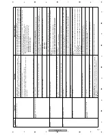
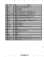
Operation
Symptom
Check Item
Measures to be taken
Misc.
Remote control unit not effective
Check the connections:
Signals from the remote control unit may not be accepted because FL UCOM (IC501),
which handles those signals, is occupied with other key signals that are kept input, although
the remote control signals themselves are correctly processed in the FLKB.
Check the connections among the FLKB, KEYB, DRV1B, and DRV2B:
Reconnect or replace the 25-pin FFC (DDD1232) that connects the FLKB (CN503) and KEYB (CN601)
.
Reconnect or replace the 6-pin FFC (DDD1231) that connects the FLKB (CN502) and DRV1B (CN631)
.
Reconnect or replace the 6-pin FFC (DDD1231) that connects the FLKB (CN602) and DRV2B (CN641)
.
Check key input from the remote control unit for service:
Key input from the remote control unit for service is not accepted.
As each segment on the FL display corresponds to a particular key of the remote control
unit for service.
If any segment on the FL display was already unlit, there had already been key input.
To enter Front-Panel-Button-Input Test mode, press the [ESC], [TEST], then [TV/LDP] keys, in that
order. To quit Test mode, press the [ESC] key.
If it is suspected that the FLKB (DWZ1164) is defective, replace it.
Repair/replace the Assy corresponding to the inoperable key.
FLKB (DWZ1164): STB, Disp, Func, Function operation (x5)
KEYB (DWZ1157): Drv_Sel, Preview, Main operation (x8)
DRV1B (DWZ1160): Drv1_Eject
DRV2B (DWZ1161): Drv2_Eject
Repair/replace the Assy.
All or part of the FL display is dark, or no FL
display
Check the connections.
Check the connections between the PWRB and FLKB.
Reconnect or replace the 20-pin cable (DKP3637) between the PWRB and FLKB.
Check the display on the FL display, using the remote control unit for service.
To enter LED/FL Test mode, press the [ESC], [TES
T], then [P.RUN] keys, in that order.
To quit Test mode, press the [ESC] key. Check the FLKB (DWZ1164) or PWRB (DWZ1129) if all or part
of the FL display is dark.
Check the power supply for the FL display.
If the power supply from the PWRB (DWZ1129) is insufficient, replace the board.
IC301 : -23.4V
IC401 : -26.8V
IC451 : -31.2V
Misc.
The FL (DAW1019) on the FLKB (DWZ1164) is at the end of its life. Replace the FLKB board.
Installation
Installation not completed
Check the settings and connections.
Check the connections between the MB and HDD, MB and DVD_Drive 1, and between the MB and
DVD_Drive 2:
The HDD (VXF1015) must be connected to Master IDE_Primary.
The DVD Drive 1 (DVR-105-PLX) must be connected to Master IDE_Secondary.
The DVD Drive 2 (DVR-105-PLX) must be connected to Slave IDE_Secondary.
"DISK BOOT FAILURE, INSERT SYSTEM DISK AND PRESS ENTER" is displayed on the
VGA screen.
Reinstall the OS.
After replacement of the HDD, reinstall the OS.
"!!!!!!The root file system has been recovered!!!!!!!!" is displayed in the log file.
If the same message was recorded many time
s, reinstall the OS.
Parts
Inoperable CPU cooler
Check connections.
Check the connections between the MB and CPU_FAN, and among the ATX power supply, PWRB, and MB.
Reconnect the connector for the CPU cooler.
No power supply to the CPU cooler
Reconnect the 20-pin cable of the ATX power supply (DXF1005), or replace the ATX power supply.
Reconnect or replace the 20-pin cable (DKP3657) between the MB and PWRB (CN4).
The CPU cooler is defective.
Replace the CPU cooler.
Inoperable fans
Check connections.
Check the connections between the PWRB and the two fans in the front section and one fan in the rear
section:
Reconnect or replace the 2-pin relay cable (DKP3676) that connects the PWRB (CN9) and the fan at
the rear section.
Reconnect the 2-pin cable that connects the PWRB (CN10) and Fan 1 at the front section, or replace
the fan (AXM7014).
Reconnect the 2-pin cable that connects the PWRB (CN11) and Fan 2 at the front section, or replace
the fan (AXM7014).
The FAN_DET LED (D24) on the PWRB remains unlit.
If it is suspected that the fan (AXM7014) is defective, replace it.
If it is suspected that the PWRB (DWZ1129) is defective, replace it.
The unit will not start even after MB
replacement
Check connections.
Check the connections among the ATX power supply, PWRB, MB and FLKB.
Check the connections between the MB and HDD.
"CMOS checksum error-Defaults loaded" is displayed on the VGA screen.
If the BIOS data check fails, press the F1 key then reload
the BIOS values.
Check the date and time:
At startup, press the [DEL] key to check the date and time on the BIOS screen (standard
CMOS features). (The range of recognition at the APL level is from 2002.01.01 to
2037.12.31.)
Set the date and time according to the current Greenwich mean time.

