


PRV-LX10
124
1
2
3
4
1
2
3
4
C
D
F
A
B
E
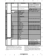
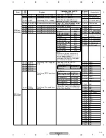
Assy
ST
LED
Function
Operation while the LED
is lit/remarks
Checker
Chip
Monitor Point
AVIB Assy
(DWV1202)
D3201 V+12I
Conf12 V supply
Outp12 V from PWRB
−
D3202 V+5DI
Conf5 V supply
Outp5 V from PWRB, normal
operation of IC3205 (ICP-S2.3)
D3203 V+3_3I
Conf3.3 V supply
Outp3.3 V from PWRB
D3204 V+2_5I
Conf2.5 V supply
Outp2.5 V from PWRB
D5001 ENC OK
Confirming Xlinx operational
status
Default: lit (Config. completed), during
ENC operation: flashing
D5002 WMKD7
Confirming encoder operational status (3)
Error indications at startup are the same
as for PCIB D2305-D2308.
D5003 WMKD6
Confirming encoder operational status (2)
D5004 WMKD5
Confirming encoder operational status (1)
D5005 WMKD4
Confirming encoder operational status (0)
Announcement functions of the LED and buzzer
Item
Function
Description
Remarks
Buzzer
1
Protection of the HD boot
sector
Protection of the HD boot sector (security function against
computer viruses)
The warning message is displayed,
with repeated peep sound.
2
Video error
This code indicates that a video error was generated. The
BIOS cannot initialize the video screen for displaying
additional data.
Following two peeps, a single beep
sounds.
3
DRAM error
This code indicates that a DRAM error was generated.
Repeated beeps sound.
LED
1
Power LED
S0 mode
LED ON
S1 mode
The LED flashes at a 1-Hz rate.
The LED flashes once per second.
S3 mode
The LED flashes at a 1-Hz rate.
The LED flashes once per second.
S4 mode
LED off
S5 mode
LED off
2
HDD LED
The LED flashes.
The LED flashes while the data are
being accessed (read/write).
3
RJ45 LED
100M
Green LED ON
10M
Green LED OFF
Link
Yellow LED flashes
Active
Yellow LED ON
1 2 3 6
No.
Signal
1
TD+
2
TD-
3
RX+
6
RX-


