PDP-5010FD
99
5
6
7
8
5
6
7
8
C
D
F
A
B
E
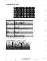
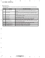
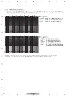
Contents of the Display item
• PM-B1 to B5: The accumulated pulse-meter counts for the 5 blocks on the screen are indicated.
(the lowest-order digit represents millions of pulses.)
• HR-MTR: The hour-meter value (accumulated power-on hours) is indicated.
• P-COUNT: The accumulated power-on count is indicated.
• TEMP1: The current panel temperature and the historical maximum temperature recorded in memory are indicated.
The range of temperature indication is from -50.0 to +99.9. (The temperature unit is "
°
C (Centigrade) ".)
• Data on operations, such as the accumulated pulse-meter counts, hour-meter count, power-on count, and temperature
detected by the sensor, are sent back. No other layers are nested below this layer, and there are no adjustment items.
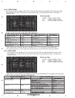
6.2.2.2 PANEL WORKS
<DOWN> : Shifting to POWER DOWN
<UP>
: Shifting to PANEL INFORMATION
<L/R>
: Updating displayed information
g
Key operation
Temperature unit is "
°
C (Centigrade) ".
A
.
P
N E L
A
P
N E L
O
W
R K S
M
P
– B 1
0 0 0
1
0
M
P
– B 2
0 0 0
1
0
0
7
5
0
2
M
M
6
0 0 0
1
0
0 0 0
0
0
1
5
8
6
8
M
M
8
0 0 0
0
0
9
6 M
2
0 0 0
2
0
8
2 M
0
H
M
P
– B 3
M
P
– B 4
M
P
– B 5
–
P
C O U
T
N
0 0 0
0
0
0
2
8
I
T
M
S
E
E
T
M P 1
+ 3
8
.
3
+ 7
1
.
5
/
R
H
– M T R
F A C T
1
5
10
15
16
1
5
10
15
20
25
30
32
1
2
3
4
5
6
7
8
9
A
B
C
D
E
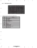
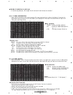
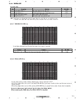
6.2.2.1 PANEL INFORMATION
• Data, such as the version of the microcomputer of the panel, product serial number, and statuses of memories for
adjustment values for the main unit and for backup, are displayed. No other layers are nested below this layer, and
there are no adjustment items.
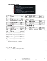
MODULE : The version of data written in the Module microcomputer (IC3601) is indicated.
-PRG
: The program version of the Module microcomputer is indicated.
-DAT
: The data version of the Module microcomputer is indicated.
SEQ-PRG : The version of data written in the Sequence LSI (IC3301) is indicated.
-PRG
: The program version of the Sequence LSI is indicated.
-PIC
: The Picture-data version of the Sequence LSI is indicated.
-SEQ
: The sequence-data version of the Sequence LSI is indicated.
SERIAL
: The serial number of the module is indicated.
DIG.EEP : The adjusted status of the EEPROM that is mounted on the DIGITAL Assy is indicated.
BACKUP : The adjusted status of the EEPROM for backup that is mounted on the SENSOR Assy is indicated.
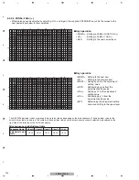
• In the following examples, GUI images for a 50-inch and 60-inch models are indicated.
<DOWN> : Shifting to PANEL WORKS
<UP>
: Shifting to COMBI MASK SETUP
(+)
<L/R>
: Updating displayed information
g
Key operation
Details of indications in each layer
Display items:
A
.
P
N E L
A
P
N
N
E
I
L
F O R
N
T
A
M
O
I
D
O
M
U L E
F A C T
V
–
D 1
1
5
0 6 0
= 0 2 F
= 0 2 F
= 0 2 F
– P R G
–
–
D A T
0 5 F
G
I
D
. E E P
A D
T
J U S
E D
A D
T
J U S
E D
C
A
B
K U P
Q
E
S
P R S
= 0 4 Y
= 0 4
= 0 3 Y
– P R Q
– P I C
R
E
S
I A L
_ _ _ _ _ _ _ _ _ _ _ _ _ _ _
– S E Q
6 2 0 Y
0 4 F
– N T V
T
A
–
B
V
–
D 1
1
5
0 6 0
– N T V
T
A
–
B
1
5
10
15
16
1
5
10
15
20
25
30
32
1
2
3
4
5
6
7
8
9
A
B
C
D
E
Содержание PDP-5010FD
Страница 19: ...PDP 5010FD 19 5 6 7 8 5 6 7 8 C D F A B E ...
Страница 20: ...PDP 5010FD 20 1 2 3 4 1 2 3 4 C D F A B E 4 BLOCK DIAGRAM 4 1 OVERALL WIRING DIAGRAM 1 2 ...
Страница 22: ...PDP 5010FD 22 1 2 3 4 1 2 3 4 C D F A B E 4 2 OVERALL WIRING DIAGRAM 2 2 V 8V_AU V 3_3V_A V 3_3V_AU_D ...
Страница 23: ...PDP 5010FD 23 5 6 7 8 5 6 7 8 C D F A B E ...
Страница 35: ...PDP 5010FD 35 5 6 7 8 5 6 7 8 C D F A B E ...
Страница 167: ...PDP 5010FD 167 5 6 7 8 5 6 7 8 C D F A B E ...
Страница 178: ...PDP 5010FD 178 1 2 3 4 1 2 3 4 C D F A B E 10 6 PANEL CHASSIS SECTION ...
Страница 182: ...PDP 5010FD 182 1 2 3 4 1 2 3 4 C D F A B E 10 8 PDP SERVICE ASSY 508F AWU1272 Exterior Section ...


