PDP-5010FD
114
1
2
3
4
1
2
3
4
C
D
F
A
B
E
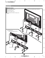
Disassembly
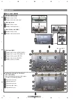
Rear Case (508F)
1
1
1
2
4
6
5
5
3
3
1
Remove the two screws.
2
Remove the function button panel.
3
Remove the two screws.
4
Remove the side input cover.
Function button panel
Side input cover
Power button
case (508F)
SIDE KEY Assy
Function button panel
Side input cover
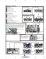
5
Remove the two screws.
6
Remove the power button case.
Power button case (508F)
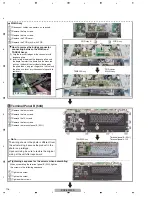
1
Remove the 20 screws. (AMZ30P060FTB)
2
Remove the 10 screws. (TBZ40P080FTB)
3
Remove the two screws. (ABA1332)
4
Remove the one screw. (ABA1341)
5
Remove the rear case (508F).
1
Tighten the two screws.
2
Tighten three screws.
3
Tighten the two screws.
4
Tighten the eight screws.
5
Tighten other screws.
Rear case (508F)
Rear case (508F)
5
1
1
1
1
1
1
1
1
1
2
2
2
2
3
2
2
2
2
3
2
2
1
1
1
1
1
1
1
4
1
1
1
1
1
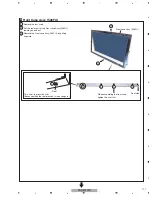
When assembling the rear case (508F), tighten
the screws in the following sequence:
Tightening sequence for the screws
when assembling
-1
2
2
3
-1
2
1
-2
4
-1
4
-2
4
-3
4
-1
4
-2
4
-3
4
-4
4
-4
3
-2
Содержание PDP-5010FD
Страница 19: ...PDP 5010FD 19 5 6 7 8 5 6 7 8 C D F A B E ...
Страница 20: ...PDP 5010FD 20 1 2 3 4 1 2 3 4 C D F A B E 4 BLOCK DIAGRAM 4 1 OVERALL WIRING DIAGRAM 1 2 ...
Страница 22: ...PDP 5010FD 22 1 2 3 4 1 2 3 4 C D F A B E 4 2 OVERALL WIRING DIAGRAM 2 2 V 8V_AU V 3_3V_A V 3_3V_AU_D ...
Страница 23: ...PDP 5010FD 23 5 6 7 8 5 6 7 8 C D F A B E ...
Страница 35: ...PDP 5010FD 35 5 6 7 8 5 6 7 8 C D F A B E ...
Страница 167: ...PDP 5010FD 167 5 6 7 8 5 6 7 8 C D F A B E ...
Страница 178: ...PDP 5010FD 178 1 2 3 4 1 2 3 4 C D F A B E 10 6 PANEL CHASSIS SECTION ...
Страница 182: ...PDP 5010FD 182 1 2 3 4 1 2 3 4 C D F A B E 10 8 PDP SERVICE ASSY 508F AWU1272 Exterior Section ...

