PDP-5010FD
119
5
6
7
8
5
6
7
8
C
D
F
A
B
E
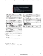
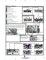
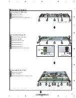
Exchange of SCAN IC
6
1
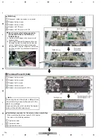
Remove the four screws.
2
Remove the two screws.
3
Remove the front chassis HT (50
8
F) Assy.
Front chassis HT (50
8
F) Assy
1
Disconnect the two jumper wires.
2
Remove the one screw.
3
Remove the FHD RLS Assy.
4
Remove the two screws.
5
Remove the two screws.
6
Remove the two screws.
7
Remove the front chassis HB Assy (50).
Front chassis HB Assy (50)
1
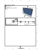
Remove the two screws.
2
Unhook the six hooks.
3
3
3
Remove the panel holders
V
1 (50) and
V
2 (50).
Panel holder V1 (50), V2 (50)
1
2
2
1
1
1
6
1
5
5
1
1
1
2
3
7
3
Front chassis HT (50
8
F) Assy
50FHD LED Assy
FHD IR
Assy
FHD RLS Assy
4
4
6
2
2
2
2
2
2
Panel holder
V
2 (50)
Panel holder
V
1 (50)
Содержание PDP-5010FD
Страница 19: ...PDP 5010FD 19 5 6 7 8 5 6 7 8 C D F A B E ...
Страница 20: ...PDP 5010FD 20 1 2 3 4 1 2 3 4 C D F A B E 4 BLOCK DIAGRAM 4 1 OVERALL WIRING DIAGRAM 1 2 ...
Страница 22: ...PDP 5010FD 22 1 2 3 4 1 2 3 4 C D F A B E 4 2 OVERALL WIRING DIAGRAM 2 2 V 8V_AU V 3_3V_A V 3_3V_AU_D ...
Страница 23: ...PDP 5010FD 23 5 6 7 8 5 6 7 8 C D F A B E ...
Страница 35: ...PDP 5010FD 35 5 6 7 8 5 6 7 8 C D F A B E ...
Страница 167: ...PDP 5010FD 167 5 6 7 8 5 6 7 8 C D F A B E ...
Страница 178: ...PDP 5010FD 178 1 2 3 4 1 2 3 4 C D F A B E 10 6 PANEL CHASSIS SECTION ...
Страница 182: ...PDP 5010FD 182 1 2 3 4 1 2 3 4 C D F A B E 10 8 PDP SERVICE ASSY 508F AWU1272 Exterior Section ...


