Pilot Communications Pitts Challenger Скачать руководство пользователя страница 5

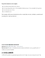
warranty is limited to construction or production defects in both material and workmanship, and does
not cover any parts damaged due to misuse or modification.

Should you wish to return this airplane for any reason, all shipping costs are the responsibility of
customer.

If any parts are needed to be replaced by the manufacturer, the original parts must be returned, at the
costumers expense.

Do not regard this plane as a toy!

The manufacturer can not supervise the assembly and maintenance of the model or ensure your correct
radio installation. Therefore, the manufacturer can not be made responsible or liable for any damage
occurring during the use of this radio controlled model. As such all responsibility for the correct build,
maintantence and operation must be accepted by the customer. The operation of the model is taken as
acceptance by the customer of their acceptance to the above.

The model is highly prefabricated and ready for use, however please also assure that any pre-installed
(such as pushrodand ball link sets, fuel tank, etc) components are tight, secure and airworthy both for
the first flight and subsequent flights as part of your routine maintenence and verification.

In no event does Pilot-RC accept any liability to exceed the original cost of the basic Pilot-Rc airframe
provided (accesories such as engine or radio system are also excluded from liability).

To ensure safety, please read the instruction manual thoroughly before assembly. Building and
operating model planes requires diligent practice and correct guidance. Any neglect, carelessness or
lack of experience can cause serious bodily harm or damage to property.

Seek the assistant of local model flying clubs and or an experienced aeromodeller for assembly,
operation and maintenance to ensure a quick and successful learning process.

Fly only at designated model flying fields approved by the AMA (Academy of Model Aeronautics), the
MAAC (Model Aeronautic Association of Canada) or the similar corresponding governing body for
your country.

Содержание Pitts Challenger

Страница 1: ...Pitts Challenger 87 2 20m 100cc MANUAL...

Страница 2: ...h all basic accessories such as carbon fiber main undercarriage tail gear assembly and wing tubes as well as fibreglass control horns and wheel pants Pre installed hinges and pre mounted canopy Fuel t...

Страница 3: ...REQUIRED HARDWARE Motor 100 120cc Servos 7 8 high torque plus throttle Uses x1 per aileron total x4 x1 per elevator and x1 or x2 on rudder...

Страница 4: ...ires all the usual accessories such as transmitter receiver batteries powerbox and possibly other small accessories PILOT RC RECOMMENDED HARDWARE Servos Pilot Rc PW27AH 27Kg 0 119s at 8 4v Servo arms...

Страница 5: ...ly prefabricated and ready for use however please also assure that any pre installed such as pushrodand ball link sets fuel tank etc components are tight secure and airworthy both for the first flight...

Страница 6: ...wn are from other models which follow the same build steps MAIN LANDING GEAR ASSEMBLY AND WING WIRES Position the fuselage upside down and screw on the carbon undercarriage to the fuselage using the n...

Страница 7: ......

Страница 8: ......

Страница 9: ......

Страница 10: ......

Страница 11: ......

Страница 12: ...tailwheel assembly you will need to attach the cross member for the elevator guide wires Insert the blind nuts on the inside of the fuselage and secure the tail wheel and cross member with the bolts...

Страница 13: ......

Страница 14: ......

Страница 15: ......

Страница 16: ...LEVATOR It is very important to sand horn to assure a strong bond once glued to the model Locate and cut the covering where the horns will be glued Glue them to the surface using epoxy glue Excess epo...

Страница 17: ......

Страница 18: ......

Страница 19: ......

Страница 20: ...RUDDER It is very important to sand horn to assure a strong bond once glued to the model Locate and cut the covering where the horns will be glued Glue them to the surface using epoxy glue Excess epox...

Страница 21: ......

Страница 22: ......

Страница 23: ......

Страница 24: ......

Страница 25: ......

Страница 26: ......

Страница 27: ...ILERONS It is very important to sand horn to assure a strong bond once glued to the model Locate and cut the covering where the horns will be glued Glue them to the surface using epoxy glue Excess epo...

Страница 28: ......

Страница 29: ......

Страница 30: ......

Страница 31: ...wing servos each aileron will require two separate extension leads The first extension lead should run inside the lower wing to the location of the outer wing strut The second extension lead should b...

Страница 32: ...the pushrods provided...

Страница 33: ......

Страница 34: ......

Страница 35: ......

Страница 36: ...pull wire carefully through the fuselage slots all the way back to the actual rudder servo Attach the ball links to the rudder servo horn and pull through any excess pull pull wire until both sides ar...

Страница 37: ......

Страница 38: ......

Страница 39: ......

Страница 40: ......

Страница 41: ......

Страница 42: ...your required extension lead to the servo allowing sufficient length for the lead to reach your receiver or Powerbox without needing further extensions Route the servo wire through the fuselage and s...

Страница 43: ......

Страница 44: ......

Страница 45: ......

Страница 46: ...ct engine incidence You can measure the distance between your engines mounting plate and prop hub and compare the distance between the firewall and spinner location in order to calculate the size of s...

Страница 47: ......

Страница 48: ......

Страница 49: ......

Страница 50: ......

Страница 51: ......

Страница 52: ......

Страница 53: ...servo simply screw the servo to the provided servo mount and then screw and glue this in its final location where required for your particular engine Use the included pushrod to connect to your engine...

Страница 54: ......

Страница 55: ......

Страница 56: ......

Страница 57: ...sking tape in line with the two bolt holes Draw a straight line on the masking tape going over the holes and mark measure where the hole is relative to the lines Install the cowling tightening the top...

Страница 58: ......

Страница 59: ...th double sided tape or velcro making sure that all servo leads can be easily connected without being too tight and that the receiver is securely fixed in place For specific tips on receiver and anten...

Страница 60: ......

Страница 61: ...Note that the two laser cut holes are for the fuel and smoke tank vents...

Страница 62: ...he two screw holes in the wheel pants Remove the wheel pants and drill the holes for the appropriate holes Before putting back on the plane mount the bolt with the blind nut on the wheel pant and tigh...

Страница 63: ......

Страница 64: ......

Страница 65: ...e tail wheel step They are secured permanently using the same crimping method as used for the rudder pull pull wires At the other end they are secured to the actual elevator using the provided accesso...

Страница 66: ......

Страница 67: ......

Страница 68: ......

Страница 69: ......

Страница 70: ...rect order and location in order to assure the correct wing angle and incidences To make setup simple inside the struts you will find laser engraved descriptions of where each side of the wing strut s...

Страница 71: ......

Страница 72: ......

Страница 73: ...eviously At the other end you will find Pilot RC s patented quick release system which allows for the guide wires to be attached or released in seconds This is due to them being permanently fixed to a...

Страница 74: ......

Страница 75: ......

Страница 76: ......

Страница 77: ...icated CG hole then proceed to setup the model fully and then lift using said wire The model should sit level when lifted Personal CG preference can then be adjusted following the first flight For ref...

Страница 78: ......

Страница 79: ...rface Deflection Expo Ailerons 20 35 Elevators 20 35 Rudder 20 20 Full 3D acrobatics Surface Deflection Expo Ailerons 40 60 Elevators 40 60 Rudder 45 35 FIELD SETUP Setup at the field can be done very...

Страница 80: ......

Страница 81: ...nder the screws and tightening 3 Attach the upper wing to both the A frame and the other side of the strut along with the servo connection 4 Attach the tension wires permanently fixed at the centre po...

Страница 82: ......

Страница 83: ......

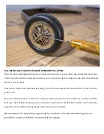
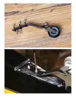
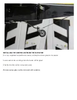
Страница 84: ...6 Secure the elevator tension wires as per picture below All this can be done in just a few minutes...

Страница 85: ...ightly secured batteries and or fuel tank are full all surfaces are working in the correct directions balance is correct and range test passed before performing your maiden flight WE WISH YOU A SUCCES...

Отзывы: