


5 Installation
24
Version: 2.5.1
MS201E
H-840 Hexapod Microrobot
5.2
Determining the Permissible Load and Workspace
Tools and Accessories
PC with Windows operating system with the PI Hexapod Simulation Tool installed. For
further information, see the A000T0068 technical note.
Determining the workspace and the permissible load of the hexapod
Follow the instructions in the A000T0068 technical note to determine the workspace
and the limit value for the load of the hexapod with the simulation program.
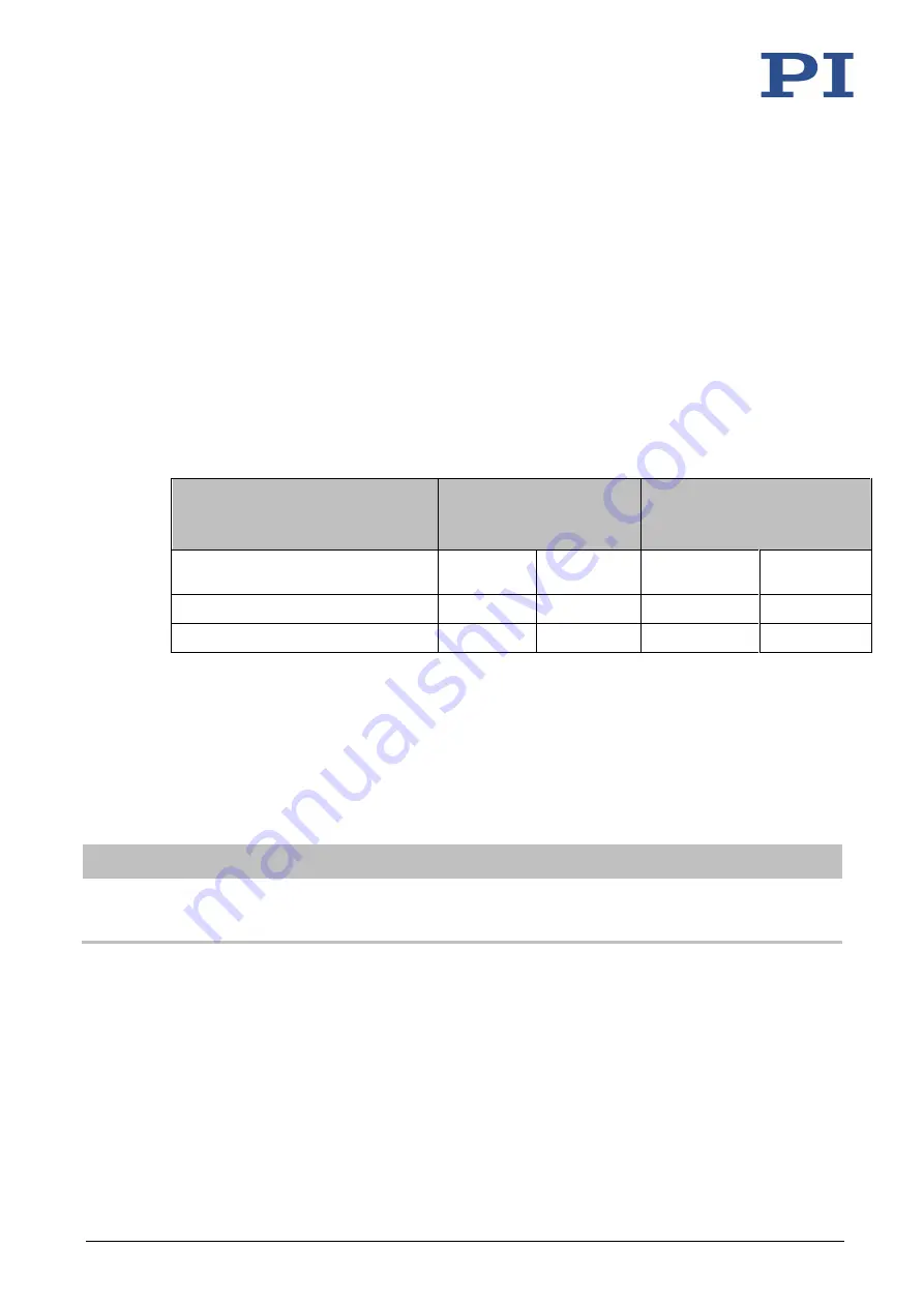
The limit values in the following table serve as a guide. They only apply when the center of mass
is at the origin of the default coordinate system (0,0,0).
Servo mode switched on
for hexapod –
Max. load capacity
Servo mode switched off for
hexapod –
Max. holding force
Mounting position of the base plate
Mounted
horizontally
Mounted in
any direction
Mounted
horizontally
Mounted in
any direction
H-840.G2A, .G2I, .G2IHP
30 kg
10 kg
100 N
25 N
H-840.D2A, .D2I
10 kg
3 kg
15 N
5 N
If you need help on determining the limit value for the load or determining the workspace:
Contact our customer service department (p. 45).
5.3
Grounding the Hexapod
INFORMATION
If there is any vibration in your application, secure the screw connection for the protective
earth conductor in a suitable manner (e.g., with conductive liquid adhesive) to prevent it
from unscrewing by itself.
The hexapod is not grounded via the power supply cable. If a functional grounding is required
for potential equalization:
1.
Connect the base plate to the grounding system:
−
For connection, use the supplied accessories (p. 9) and the M4 hole with an 8 mm
depth marked with the ground connection symbol (p. 57).
2.
Connect the motion platform to the grounding system:


