


9
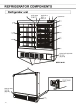
REFRIGERATOR COMPONENTS
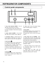
1. Control panel:
The chamber temperature and alarms can be set through the keys on the control
panel. The temperature display and indicators are also provided on the control panel. Refer to page 10
for details.
2.
Location of battery kit for power failure alarm:
The battery kit (optional) alerts the power failure by
the alarm indicator and alarm buzzer.
3.
Door switch:
This switch detects the door status (open/close). The door check lamp is ON when
the door is open.
4.
Door:
Sliding type. The recessed portion on the rail enables the self-closing of the door. The glass
is pair construction.
The condensation may be found on the door frame with ambient humidity of about 50%R.H. and on the
glass surface with ambient humidity of about 60%R.H. This is not a malfunction.
The condensation on the door is dropped on the rail and exhausted to the evaporating tray.
5.
Air exhaust vent:
Do not block this vent. Arrange the stored items not to subject to the cold air
from the vent.
6.
Drawer (Right side of MPR-1014R):
To pull out the drawer, take out the drawer with pushing the
button at the bottom of the drawer.
<Important>
Never pull out the multiple drawers at a time. It may cause tipping over of the unit.
7.
Air intake vent (front bottom):
Do not block this vent. Blocking this vent may cause unstable
chamber temperature. Do not insert fingers or similar articles into the vent.
8.
Filter:
Clean the filter once a month. Refer to page 28.
9.
Evaporating tray:
Defrost water from the evaporator accumulates in the tray and evaporates into the
atmosphere. See page 27 for cleaning.
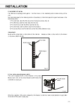
10. Leveling foot (front, 3 locations):
These are used for install the unit. Adjust the height of the
leveling feet by turning the screw bolts until 3 front casters are away from the floor.
11.
Shelf:
The set location is adjustable.
Items to be stored in the chamber must be placed on the shelves. Do not put stored items directly on
the bottom of the chamber.
12. Access port:
This port allows a sensor or cable of measuring equipment to enter the chamber from
outside.
Replace insulation and the rubber caps when the access port is not used. Improper replacement may
cause rise of chamber temperature or condensation around the access port.
13. Exclusive alarm sensor:
A sensor for detecting the temperature rise at the upper area of the
chamber. Refer to page 23 for alarm functions.
14.
Back spacer (also used as a fixture):
To keep the space between the unit and the back wall for
adequate cooling performance. And this can be used as a fixture. Fix the unit by using the fixture and
a rope or chain. Refer to page 12.
15.
Circuit breaker switch:
Switch ON this circuit breaker switch before the unit starts to run. Refer to
page 13.
Содержание MPR-1014 Series
Страница 2: ......


