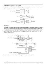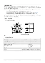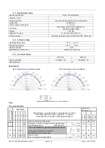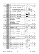
Datei/ file name:085501929k de-en-fr-it.docx
page 27 / 66
Drwg-no.: 30007-008-12k
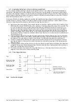
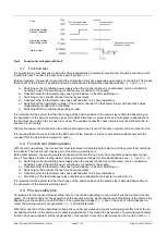
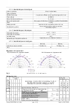
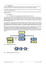
Fig. 9
Function time diagram with fault
4.7. Function test
For applications in 'low demand mode' with safety requirements an automatic function test should be carried out with
regular intervals. The test intervals can be seen in section
Both part systems, the sounder channel and the monitoring circuit, have separate power supply connections. This means
that a check of the function is possible and can be carried out as follows (time dependencies see
).
a) Switching on the monitoring power supply when the sounder channel is not activated, (can be omitted de-
pending on use if the monitoring is continuously connected to the supply)
b) Check whether the fault alarm relay has high-resistance >0.5s after switching on,
c) Switching on the sounder channel (sound is generated)
d) Check whether the fault alarm relay has switched after >0.2s (low-resistance)
e) Switching off the operational voltage of the sounder channel, the fault alarm relay must have fallen away
(high-resistance) after 2.5s at the latest
f)
Switching off the monitoring (depending on use)
It is important for the system test that the change of the switch position of the alarm relay is detected depending on
the generation of the acoustic warning signal. With which distances a system test has to take place is dependent on
the eventual use in which the sounder is involved. The equipment specific check intervals must be defined in the re-
spective proof of safety.
The function test can be shortened if a tone without interrupted tones is used. Then time in point e) can be reduced to 0.3s.
It is required that a tone is selected at the DIP switch of the sounder or a tone is activated simultaneously with the
sounder from the 'external tone selection' option.
4.8. Function test (Starting alarm)
With the start-up warning, the function test must take place immediately before start-up of the system that could lead
to a hazard. The function test may be part of the start-up warning here.
Both partial systems, the sound generator channel and the monitoring circuit, have separate power supply connec-
tions. This enables function testing which can be performed as follows (for time dependencies see
a) Switching on the monitoring power supply when the sounder channel is not activated, (can be omitted de-
pending on use if the monitoring is continuously connected to the supply)
b) Check whether the fault alarm relay has high-resistance >0.5s after switching on,
c) Switching on the sounder channel (sound is generated)
d) Check whether the fault alarm relay has switched after >0.2s (low-resistance)
e) Monitoring of the fault message relay until start-up is enabled but at least for a period of >3 s
It is important for the system test that the change of the switch position of the alarm relay is detected depending on
the generation of the acoustic warning signal.
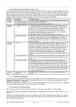
4.9. Process safety time
Conclusions for the required process safety time can be drawn depending on use according to the function time dia-
grams. The reaction times for the generation of the acoustic warning signal and the switching status of the alarm relay
depending on the switching on and off time of the operational voltage (
) and in the case of a fault (despite de-
mand, the warning signal is not generated,
) are illustrated here.
With the connection of the operational voltage, the sounder generates an acoustic warning signal after 0.3s at the lat-
est and reports this via the alarm relay (output low-resistance). This means the 'generation of a warning signal' safety
function has been activated. Further explanations of the reaction times of the alarm relay can be found in section
Tone
Operating voltage
Sounder channel
Operating voltage
Monitoring circuit
Alarm output
Tone is not generated
Tone cancelled
* dependent on the tone
and cause of fault

