Datei/ file name:085501929k de-en-fr-it.docx
page 28 / 66
Drwg-no.: 30007-008-12k
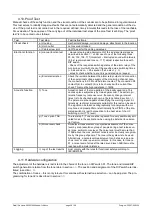
4.10. Proof Test
Manual checks of the safety function and the visual condition of the sounder are to be performed in regular intervals.
This test serves to identify dangerous faults that are not automatically detected and the general condition of the de-
vice. If the proof test is not carried out in the required, defined, timely intervals this leads to the loss of the reachable
SIL evaluation. The sequence of the carrying out of the individual test steps of the proof test is arbitrary. The 'proof
test' is to be carried out as follows:
Test
Test step
Test instructions
Visual check
a.) Housing
mechanical damage, corrosion damage, attachment to the location
b.) Horn outlet
not covered or locked
c.) Cable screw joint
tight fit, seal for the cable guaranteed
Electronic function
d.) manual function test
- manual, step-by-step deployment of the individual test steps as
described in section
under use of one of the following tones:
90, 92, 100, 108, 117 (Important
– interrupted sound with intervals
>0.5s!, recommended tone no. 117), adjust respective tone with
DIP switch
- Check of the respective switching status of the alarm relay of the
monitoring circuit with check of the specified max. switching times
(< 0.2s sound on, < 2.5s sound off, see also
- acoustic check whether a sound is generated upon request
e.) Electrical isolation
Check the isolation between the alarm relay output and connection
of the operational voltage supply of the monitoring channel. Also,
the connections to X3 should be disconnected. The connection X3
contact 3(4) to contact 5(6) is to be checked with a current flow
check. This must be high-resistance (>1M
Ω).
Acoustic function
f.) Tone
Acoustic check of the tone pattern of the locally used tone. This
can take place subjectively by trained personnel. The pattern (in-
tervals, frequency response curve, frequency change, interval
times) is to be checked as shown in the tone table in section
The person must be capable of identifying the warning signal. Al-
ternatively, technical implements suitable for this test can be used.
The signal can be taken oscillographically for analysis with a mi-
crophone and preamplifier or electronically from PIN13 of the inte-
grated switch U4 (earth connection to the heat sink of the U3
switching circuit, TTL level).
g.) Tone option TAS
The test step 'f.) Tone' must be repeated for every additionally acti-
vated tones in the application when using the 'external tone selec-
tion' option.
h.) Noise level check
Noise level measurement or subjective assessment of the noise
level by a representative group of people during a test release un-
der max. ambient noise level. The noise level must be more than
+10dB above the max. ambient noise level or be clearly recogniza-
ble by this group of people. The tone in the system is to be used.
Alternatively, a noise level measurement can be taken in an ane-
choic room or under open-air conditions. In this case, for tone no.
57, a noise level of at least the rated sound level -3dB(A) must be
reached with a meter distance.
Logging
i.) Log of the test results
must comply with the rules for functional safety according to
IEC/EN61508
4.11. Hardware configuration
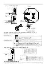
The adjustment of the hardware is restricted to the choice of the tone on DIP switch S1. The tone and related DIP
switch generation is taken from the tone table in section
. The position and assignment of the DIP switch are illus-
trated in section
The combination of tones
– this is only relevant for versions with external tone selection – can be adjusted. The pro-
gramming for tone 32 is described in section

