


Adjustment
18
15
.06.11
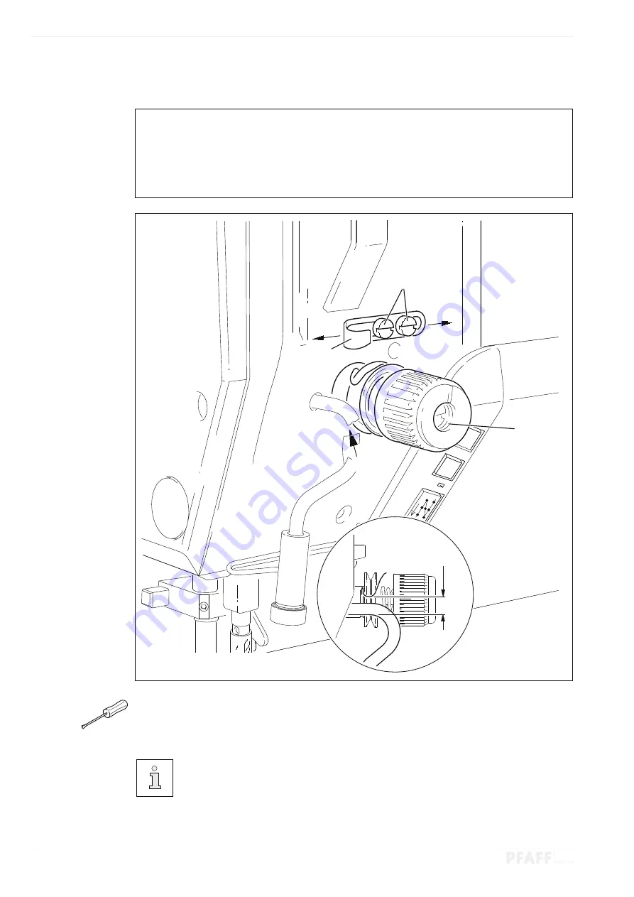
Thread check spring and slack thread regulator
Rule
1. The movement of the thread check spring should be finished when the needle point
punctures the material ( spring deflection: approx.
7 mm
).
2. The thread check spring should have moved approx.
1 mm
when forming the maxi-
mum thread loop while passing the thread around the hook.
O
Turn the thread tension
1
( screw
2
) according to
rule 1
.
O
Adjust the slack thread regulator
3
( screws
4
) according to
rule 2
.
It may be necessary to deviate from the specified spring deflection for reasons
relating to the sewing technology.
Adjust the slack thread regulator
3
(screw
4
) by “
+
” (= more thread) or
“
-
” (= less thread).
Fig. 15 - 12
7
mm
4
3
-
1
+
2