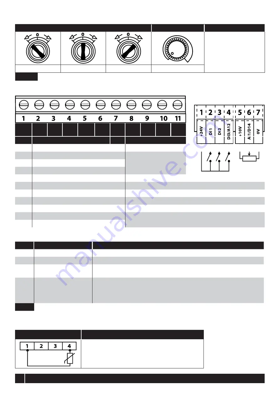
Switched Units: Default functions of the control switches
Switch Position
POT
Notes
Factory Default
Configuration.
Run Forward or Reverse
with speed controlled from
the Local POT.
Run Reverse
STOP
Run Forward
Sets the output frequency
NOTE
Other functions are possible, please refer to the online documentation for additional information.
Using the Control Terminals
Connection Example
Factory Default Functions
No.
Description
DI1
0/1
Open : Stop
Closed : Run
DI2
3
/
4
Open : Forward Rotation
Closed : Reverse Rotation
DI3
Analog Speed Reference /
Preset Speed
Open : Speed Reference set by Analog Speed Reference
Closed : Speed Reference set by Preset Speed 1 (P-20)
AI1
Analog Speed Reference
Input
Sets the Speed Reference
NOTE
For Switched units, the internal pot is selected by default in P-16.
For Non-switched units, an external pot or 0 - 10 V reference may be connected. Other
signal types may also be used, set P-16 to the correct format.
NOTE
Additional functions are possible, refer to the online documentation for further information.
Motor Thermistor Connection
Where a motor thermistor is to be used, it should be connected as follows:
Control Terminal Strip
Additional Information
Compatible Thermistor: PTC Type, 2.5kΩ trip level.
Use a setting of P-15 that has Input 3 function as External Trip,
e.g. P-15 = 3. Refer to online documentation for further details.
Set P-47 = “
SWFWK
"
5 CHECK
+24
VDC
DI1
DI2
DI3
AI2
+10
VDC
DI4
AI1
0V
A0
0V
RL1
RL2
Nr.
Purpose
Function
1
+24 VDC 100 mA Output
24 VDC Output
2
DI1 Digital Input 1
Function defined by
P-12 & P-15.
See below for futher info
3
DI2 Digital Input 2
4
DI3 Digital Input 3/AI2 Analog Input 2
5
+10 VDC 10 mA Output
10 VDC Output for external potentiometer
6
DI4 Digital Input 4/AI1 Analog Input 1
Function defined in P-12 & P-15. Signal format selected in P-16
7
0 VDC Common
8
AO Analog Output/Digital Output
Funktion selected in P-25. See Parameter list
9
0 VDC Common
10
RL1 Output Relay
Function defined in P-18. See Parameter list
11
RL2 Output Relay


