28
Innehåll
28
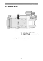
Seat angle mechanism
Seat angle mechanism
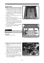
Removal
1.
Raise the seat; electric seat lift to the highest
position; fixed seat tube to the service position.
See page 28. If the electric seat lift does
not work normally because the batteries
are discharged or the adjustment device is
defective, the seat can be raised/lowered
manually. See page 26.
2.
Switch off the main power switch on the
control panel.
3.
Remove the upper and rear chassis cover.
See page 8.
4.
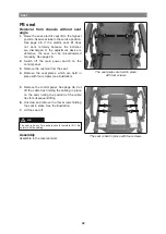
Remove the seat. See pages 32–35.
The seat is heavy. Two people should therefore lift it. Be
careful with the cabling.
m
nB
5.
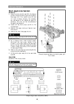
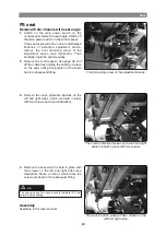
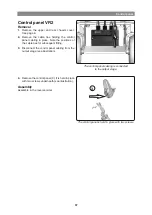
On a chassis with a VR2 control system,
disconnect the seat angle cabling at the
contact on the output stage (see illustration
below). Cut the cable ties holding the cabling
in place, noting the position of the cable ties
for subsequent fitting.
6.
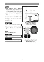
Remove the seat angle by unscrewing the four
screws. See the illustration.
7.
Lift the seat angle away from the seat tube/
seat lift.
The seat angle mechanism is held in place with
four screws.
assembly
Assemble in the reverse order.
Make sure that the hole on the seat angle is correctly positioned
against the corresponding hole on the seat lift/seat tube.
m
nB
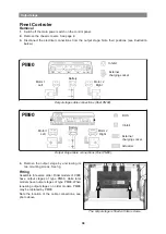
Output stage cable connections (VR2).
Motor 1
Left
Motor 2
Right
Battery
Inhibit
External
charging socket
Adjustment device
Control panel
Содержание C300
Страница 1: ...SERVICE MANUAL Permobil K C300 Power wheelchair US ...
Страница 2: ......
Страница 62: ...62 Cabling overview A B C D E F 1 2 3 4 ...
Страница 63: ...63 Cabling overview Cabling overview R net A B C D E F 5 6 7 8 ...
Страница 64: ...64 Cabling overview A B C D E F 1 2 3 4 ...
Страница 65: ...65 Cabling overview Cabling overview VR2 A B C D E F 5 6 7 8 ...
Страница 67: ......
Страница 68: ...Order no 205221 US 0 ...

