Assembly and Operation Manual
14
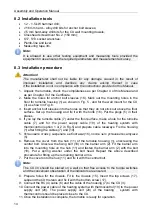
8.2 Installation tools
1.2 - 1.5 kW hammer drill;
16 mm hard – alloy drill bits for anchor bolt sleeves;
5 mm hard-alloy drill bits for the CU wall mounting dowels;
Crosshead screwdriver No. 2 (150 mm);
S17, S13 socket wrenches;
Plumb-line and level;
Measuring tape 3m.
Note:
It is allowed to use other testing equipment and measuring tools provided the
equipment in use ensures the required parameters and measurement accuracy.
8.3 Installation procedure
Attention!
The manufacturer shall not be liable for any damage caused in the result of
improper installation and declines any claims arising thereof in case
if the installation is not in compliance with the instructions provided in this Manual
.
1. Unpack the turnstile, check the completeness as per Chapter 4 of this Manual and
as per Chapter 3 of the Certificate.
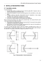
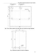
2. Make the holes for anchor bolt sleeves (16). Mark out the mounting holes in the
floor for turnstile housing (1) as shown in Fig. 5 , and for the wall mount for the CU
(3) as shown in Fig. 6.
3. Insert anchor bolt sleeves into the holes so that they do not stick out above the floor
surface. Set up the housing and fix it with the bolts (16). Put the plugs (5) in their
places.
4. If you lay the turnstile cable (7) under the floor surface, make a hole for the turnstile
cable (7) and for the power supply cable (19) of the heating system with
thermocontrol (option 1 or 2 in Fig.5) and prepare cable raceways. Fix the housing
(1) after fitting the cables (7) and (19).
5.
Установите
стойку
,
закрепите
ее
болтами
(16),
после
чего
установите
заглушки
(5).
6. Remove the cover from the hub (11) of the turnstile housing (1), unscrewing the
central bolt. Unscrew the fixing bolt (18) on the barrier arm (2). Fit the barrier arm
into the mounting hole on the hub (11) and fasten the barrier arm (2) with the bolt
(18). Put a spring washer under the bolt head. Repeat the above described
procedure for fitting up the remaining barrier arms.
7. Put the cover onto the hub (11) and fix it with the central bolt.
Note:
The CU (3) should be placed on a wall so that free access to the toggle switches
and the convenient observation of the indicators are ensured.
8. Prepare holes for the dowels. Fit in the dowels (15). Insert the top screws (17),
suspend the CU thereon and fix it with the bottom screw (17).
9. Connect the RC (4) cable (6) and the cable of the housing (7) to the CU (3).
10. Connect the power cable of the heating system with thermocontrol (19) to the power
supply unit (20). The power supply unit (20) of the heating system with
thermocontrol should be placed close to the CU.
11. Once the installation is complete, the turnstile is ready for operation.
Содержание TTR-04CW-24
Страница 1: ......
Страница 2: ...Electromechanical Tripod Turnstile PERCo TTR 04CW 24 Assembly and Operation Manual...
Страница 24: ......
Страница 26: ...www perco com export perco ru...


