background image

Boiler  Control Instruction  & Operation  Manual, Rev 1 

Page 

40 

of 64 

Setup & Tuning


Parameter Adjustment 


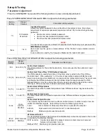
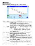
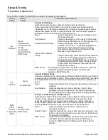
Press FROST PROTECTION CONFIGURATION to adjust the following parameters. 

Factory 

Setting 

Range / Choices 

Parameter and Description 

Enabled 

Enable/Disable 

CH Frost Protection 

Disable     Frost Protection is not used. 
Enable     Boiler and system circulators start and boiler fires when low outside 

air, supply and return temperatures are sensed as follows: 


Device 

Start Temperatures 

Stop Temperatures 

Boiler Pump 

System Pump 

Outside Air < 32°F 

Supply Water < 45°F 

Outside Air > 36°F 

Supply Water > 50°F 

Boiler 

Supply Water < 38°F 

Supply Water > 50°F 


32 (ºF) 

-50 to 50 (ºF) 

CH Frost Protection Setpoint 

Outdoor Temperature at which pumps are started for frost protection. 

 
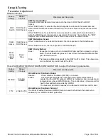
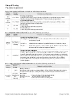
Press BURNER CONTROL TIMINGS & RATES to adjust the following parameter. 

Factory 

Setting 

Range / Choices 

Parameter and Description 

Model 

Dependent 

Min to Max Lightoff 

Rate  

(Model dependent) 

Lightoff Rate


This is the blower speed during ignition and flame stabilization periods. 

 
Press SYSTEM CONFIGURATION to adjust the following parameters. 

Factory 

Setting 

Range / Choices 

Parameter and Description 

Fahrenheit 

Fahrenheit 

Celsius 

Temperature Units


The Temperature Units parameter determines whether temperature is 
represented in units of Fahrenheit or Celsius degrees. 

1 Min 

0 to 20 Min 

Anti-Short Cycle Time 

Anti-short cycle is a tool that helps prevent excessive cycling resulting from a fast 
cycling enable-disable input (STAT terminal). It provides a minimum delay time 
before the next burner cycle. DHW demand is serviced immediately, without any 
delay. 


Содержание PureFire PFC-2000

Страница 1: ...PureFire Boilers PFC 2000 PFC 2500 PFC 3000 PFC 3500 PFC 4000 Gas Boiler Control Instruction Operation Manual ...

Страница 2: ...etup 44 Troubleshooting General Issues 45 Sensor Status 48 Limit String Status 49 Holds 50 Lockouts 52 History 55 Specifications General 58 Parameter Summary 60 Application The Peerless Boiler Control Control has been designed for commercial hot water boiler applications Intent This instruction manual includes detailed functional installation a n d setup information The intended users are applicat...

Страница 3: ...Priority DHWP Option Option Ignored Ignored Ignored Ignored Warm Weather Shutdown WWSD Option Option Option Option Option Ignored Call For Heat Call For Heat Based on Setpoints Based on Setpoints Based on Setpoints Based on Setpoints Input RO or Modbus Based on Setpoints Modulation Rate Firing Rate Demand Internal From Sequence Master Internal From Sequence Master Input 4 20mAdc or Modbus Ignored ...

Страница 4: ...s supply water temperature differential water temperature and stack temperature safety limits as well as stepped modulation responses Boiler modulation is adjusted when required to help avoid loss of boiler operation due to exceeding limits Additionally the Control monitors the safety limits and displays cause of boiler alarm trip and start delay Outdoor Air Reset When selected the active setpoint...

Страница 5: ...m Hardwired Connections Boiler On Off Switch Low Water Cutoff Switch High Limit Auto Reset Supply Supply Temperature Sensor Vestibule and Burner Thermal Fuses Min Max Air Press Switches Variable Fresh Air Supply Modbus RS 485 Monitoring Control Enable Disable Remote Firing Rate Remote Setpoint Fuel Supply Figure 3 Boiler Control Lockout Indicator Enable Disable Input Boiler Running Contact Optiona...

Страница 6: ... Hot Water DHW call for heat is on and selected as the priority demand DHW is always higher priority than Central Heat It also has higher priority than the Sequencer Control when DHW priority is enabled and Boiler Piped IWH is selected 3rd Central Heat Central Heat call for heat is on and there is no DHW demand or DHW priority time has expired 4th Frost Protection Frost Protection is active and th...

Страница 7: ...nd the Supply temperature is greater than setpoint minus the Diff Below Prepurge When supply temperature drops below setpoint minus the Diff Below burner demand continues with following Status shown Safe Startup Flame circuit is tested Drive purge The blower is driven to the fan purge speed Prepurge After the blower reaches the fan purge speed setting the 30 second combustion chamber purge is cond...

Страница 8: ... ten times the boiler manual reset Hard Lockout is set Additionally if the supply temperature rises faster than the 4 F 2 C per second limit a soft lockout is activated Return Higher Than Supply Temperature The Control monitors the supply and return temperature sensors If the return water temperature exceeds the supply water temperature for longer than a limit time delay the Control shuts down the...

Страница 9: ... CH Enabled Termp Setpoint lead boiler demand active ILK OFF LCI OFF Warm Weather Shutdown Frost Protection On CH Enabled DHW Enabled Blower Output Alarm Relay System Pump DHW Pump Isolation Valve Lea d Boiler Onl y Boiler Pump Notes System Pump Runs when boiler room has heat demand enabled Is shut off when boiler is in Warm Weather Shutdown WWSD DHW Pump Runs when there is a domestic demand Isola...

Страница 10: ... Heat demand may be received from STAT terminal for Central Heat demand S6 terminal for Domestic Hot Water demand the Sequence Master or EMS Modbus Inputs A Heat Demand input ON initiates pumps and Fresh Air Damper outputs LCI Load Control Input The boiler will not start if the LCI is OFF when it is turned OFF during run the boiler shuts down Hold message is shown when LCI limit is OFF and Heat De...

Страница 11: ...air reset setpoint saves fuel by adjusting the active setpoint of a heating boiler lower as the outside air temperature increases Domestic Hot Water DHW Setpoint User May select the Supply sensor or DHW Sensor as Modulation Sensor Upon a DHW call for heat the setpoint is either the user entered DHW setpoint or the time of day input DHW setpoint The optimal value of this setpoint is established bas...

Страница 12: ...y be selected to run first during winter months and then selected to run last for the remainder of the year DHW Two boiler Start When the Indirect Water Heater IWH parameter is set to Primary Piped and the DHW Two Boiler Start parameter is set to Enabled two boilers are started without delay in response to a DHW call for heat This feature allows rapid recovery of large IWH s and multiple IWH s Fig...

Страница 13: ...when the water temperature is outside the user selected Difference Above and Difference Below settings Also in order to minimize temperature deviations the control adjusts the number of boilers running based on the firing rate This combination allows the boilers to anticipate slow load changes before they disrupt water temperature yet still respond quickly to sudden load changes These special sequ...

Страница 14: ... the Sequence Master Control is powered down disabled or Boiler to boiler communication is lost The following are design considerations for backup Stand Alone operation Enable Disable Upon loss of the Sequence Master each boiler will automatically begin local control This means it will operate only if it has a call for heat For this reason slave boilers should have their External Enable Disable J8...

Страница 15: ...vide a walk through boiler operation These screens provide an overview of boiler operation The diagnostics screens include Modulation and Pump Tests Burner Control I O status Digital I O status and Analog I O status DETAILS Status and details are provided on all sensors connected to the Control as well as cycles and run times for the burner and pumps HISTORY Shows log of recorded issues during ope...

Страница 16: ...iew of the current status of the control s primary inputs Demand STAT LCI ILK Interrupted Air Switch and outputs Pilot Gas Valve Main Gas Valve External Ignition A green circle next to the I O name indicates that I O is currently receiving producing voltage Digital I O This page gives the current status of all of the digital on off inputs and outputs on the control Inputs include Central Heat dema...

Страница 17: ...gory is shown on each page as well as current setpoint active sensor and much more A screen map is shown below Manual Figure 12 Detail Screen Map Detail Pages Central Heat Domestic Hot Water Burner Control Demand Modulation Fan Central Heat pump DHW pump Boiler pump Flame Detection Statistics Delta T inlet outlet Outlet T rise CH Frost Protection Lead Lag Slave Relevant Sensor Page Navigation ...

Страница 18: ...Factory Setting Range Choices Parameter and Description 30 ºF 50 to 32 ºF Minimum Outdoor Temperature 70 ºF 35 to 100 ºF Maximum Outdoor Temperature 110 ºF 70 to 180 ºF Low Water Temperature 130 ºF 50 to 185 ºF Minimum Boiler Water Temperature Response Factory Setting Range Choices Parameter and Description 3 1 to 5 Central Heat Response Speed 0 0 to 30 Minutes Central Heat Low Fire Hold Time 3 1 ...

Страница 19: ...Boiler Control Instruction Operation Manual Rev 1 Page 18 of 64 Installation Terminal Layout Figure 13 Control Terminal Layout and wiring note ...

Страница 20: ... boiler Separately the Display COM 3 port Internal System Menu on each boiler is used to communicate RS485 Modbus to the Energy Management System EMS These communications are electrically separate from each other and make the connection between boilers using a common RJ45 Module and Ethernet Cable Note Display to EMS wiring Function COM 2 Terminal RJ45 Terminal RS485 Pin 4 Pin 1 RS485 Pin 5 Pin 3 ...

Страница 21: ...ndard Ethernet type cables to make connection between boilers When more than two boilers are connected an RJ45 splitter may be used to connect the boilers Refer to Figure 15 4 Set Unique Boiler Addresses Assign all boilers a unique Boiler Address using any number from 1 through 8 Found in Home Screen Configure Lead Lag Slave Configuration NOTE When two boiler s addresses are the same undesirable s...

Страница 22: ... Sequencer enabled Control The header sensor is installed on the common system piping and provides blended temperature information to the Sequence Master Refer to boiler manual s piping diagram for installation location and Figure 15a or 15b for installation detail Figure 15a Direct Immersion Type Header Sensor Installation Detail Figure 15b Thermowell type Header Sensor Installation Detail ...

Страница 23: ...mmunication Communication must be enabled Go to COM2 menu Press Setup Display Setup COM2 tab and press Enable COM2 port Then press the Gateway tab and select Enable Modbus gateway and Gateway on COM2 port 3 Set Unique Modbus Addresses COM1 Port Address The EMS Modbus address may be independent to the Boiler number or boiler address MB2 Address Go to Control Setup Press Setup Control Setup and sele...

Страница 24: ...efore entering the Setup Menu Display Communication Port Setup COM Port Com 1 Com 2 Com Port Configure For Control EMS Port Type Modbus Master Modbus Slave Special Notes Caution Do not change the baud rate of this port Loss of communication to control could result Note This is the port to adjust settings to suit the EMS System Modbus Address Range 1 8 1 8 COM Mode fixed RS485 RS485 Baud Rate 38400...

Страница 25: ...onds default 30 seconds CH Modbus Stat is reverted to 0 no demand W 203 Burner on off Burner On Off burner 1 on 0 off R 6 Demand source 0 Unknown 1 No source demand 2 Central heat 3 Domestic hot water 4 Lead Lag slave 5 Lead Lag master 6 Central heat frost protection 7 Domestic hot water frost protection 8 No demand due to burner switch turned off 9 Domestic hot water storage 11 Warm weather shutd...

Страница 26: ...Lag master setpoint source 0 Unknown 1 CH setpoint 2 CH TOD setpoint 3 Outdoor reset 4 Remote control 4 20mA 5 DHW setpoint 6 DHW TOD setpoint 7 Outdoor reset time of day 8 Mix setpoint R 10 018 Active LL setpoint 40 F 40 C to 266 F 130 C Setpoint determined by LL setpoint source register 162 R 10 643 Low Temperature setpoint Setpoint entered on the local user interface valid range 79 F 26 1 C to ...

Страница 27: ...dual boiler firing rates This register is used when firing rate control is performed by an external building automation system Firing rate reverts to local control when register is not written every Modbus Command Time Out parameter seconds default 30 seconds Range is 0 to 200 provides 0 100 firing rate W 8 Fan Speed Measured Speed of the combustion air blower in rpm R 9 Fan Speed Commanded Speed ...

Страница 28: ... Open 3 Boiler Safety Limit Open ILK Off 7 Return sensor fault 8 Supply sensor fault 9 DHW sensor fault 10 Stack sensor fault 11 Ignition failure 13 Flame rod shorted to ground 14 Delta T inlet outlet high 15 Return temp higher than supply 16 Supply temp has risen too quickly 17 Fan speed not proved 23 24VAC voltage low high 25 Hardware Fault 27 Ignition Failure R Statistics 763 Modbus command tim...

Страница 29: ...p status See Table 9 R 128 129 Burner cycle count 0 999 999 U32 R W 130 131 Burner run time Hours U32 R W 132 133 System pump cycle count 0 999 999 U32 R W 134 135 DHW pump cycle count 0 999 999 U32 R W 400 138 400 139 Boiler pump cycle count 0 999 999 U32 R W Status Description 92 Forced On from manual pump control 93 Forced On due to Outlet high limit is active 94 Forced On from burner demand 95...

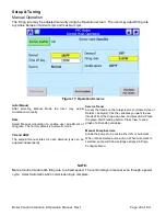
Страница 30: ...nt manual rates for each demand type can be adjusted independently Service Trend Access the trends on the Analysis screen Home Screen Details Analysis Pick the variables you want to view trends of from the drop down box and press Add Press the green Start Trending button Press View to see a graph of all trending variables Manual Pump Exercise Allows the pumps to be set to either ON or Automatic Wh...

Страница 31: ...these settings Parameters are locked and login requirement is shown when the padlock icon is closed Press the Lock icon to access password screen Use keypad to enter Password Press OK Key when complete Adjusting Parameters Editing parameters is accomplished as follows Figure 19 Adjusting Parameters white Figure 18 Security System Press the up down arrows to edit the value incrementally Press OK to...

Страница 32: ... used when a time of day timer relay is wired to the Time Of Day Controller Input When setback is on the time of day setback setpoint shifts the reset curve to save energy while building is in a reduced room temperature mode The reset curve is shifted by the difference between the High Boiler Water Temperature and the TOD Setback Setpoint Any time of day timer may be used to provide the input to t...

Страница 33: ...al ramp in less time i e faster Integral is a secondary PID modulation rate tuning adjustment that ramps the output over time typically minutes Based on the selected Local PID P select the corresponding from above table Integral value Repeats per minute between 0 5 and 2 0 are typical The burner modulation rate can oscillate if the Integral time is too large Outlet Sensor Outlet Sensor S5 J8 11 Se...

Страница 34: ...oiler Water Temp Min Boiler Temp and Central Heat Setpoint and Boost Time parameters 30 ºF 50 to 32 ºF Minimum Outdoor Temperature The Low Outdoor Temperature parameter is also called Outdoor Design Temperature This parameter is the outdoor temperature used in the heat loss calculation It is typically set to the coldest outdoor temperature 70 ºF 35 to 100 ºF Maximum Outdoor Temperature The High Ou...

Страница 35: ...from Central Heat to satisfy a Domestic Hot Water call for heat 180 50 to 190 ºF DHW Setpoint The Domestic Hot Water DHW Setpoint parameter is used to create a boiler water temperature setpoint that is used when DHW heat demand is on When the DHW heat demand is not on the contact is open or not wired this setpoint is ignored 170 ºF 50 to 190 ºF DHW Time of Day TOD Setback Setpoint The TOD setpoint...

Страница 36: ...HW Sensor Boost during priority time Boost Drop DHW Priority Method Boost Sequencer to respond to an Isolated DHW demand that is piped to a single boiler The individual boiler goes on Leave from the Sequencer Master and goes to DHW Service Drop The Sequence Master responds to the DHW Call For Heat This allows one or more boilers to provide heat to the IWH Press WARM WEATHER SHUTDOWN CONFIGURATION ...

Страница 37: ...te After ignition and flame stabilization periods the firing rate is held at low fire for Low Fire Hold Time This delay allows heat to travel out to the system and provide system feedback prior to the control modulating firing rate 1200 RPM 1200 to 1300 RPM Central Heat Domestic Hot Water Forced Rate Low Fire Hold Rate is the modulation rate the boiler will fire at for the duration of the Low Fire...

Страница 38: ... DHW Low Fire Hold Rate parameter as the starting point for the slow start 20 0 to 180 Slow Start Degrees If slow start limiting is enabled and the supply temperature is less than the temperature provided by subtracting this number of degrees from the setpoint then slow start rate limiting is effective Whenever the supply temperature is above this value slow start limiting has no effect 200 min 0 ...

Страница 39: ...active DHW Pump Pump Runs during domestic hot water call for heat Domestic Hot Water Priority enable disable does not affect pump operation DHW Demand Any Demand Never Any Demand Contact B Boiler Pump Activates the Boiler Pump Combustion Air Damper and or Standby Loss Damper output according to selected function These options are determined by the check box selections found in the Control and Adva...

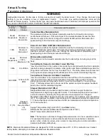
Страница 40: ...7 Days 0 to 40 Days Pump Exercise Interval The number of days the pump is inactive before the pump will be activated for the Pump Exercise Time 20 Sec 0 to 10 Min Pump Exercise Time The amount of time the pump runs for exercise This feature helps prevent pump seizing due to inactivity periods Press HIGH LIMITS to adjust the following parameter Factory Setting Range Choices Parameter and Descriptio...

Страница 41: ...e at which pumps are started for frost protection Press BURNER CONTROL TIMINGS RATES to adjust the following parameter Factory Setting Range Choices Parameter and Description Model Dependent Min to Max Lightoff Rate Model dependent Lightoff Rate This is the blower speed during ignition and flame stabilization periods Press SYSTEM CONFIGURATION to adjust the following parameters Factory Setting Ran...

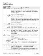
Страница 42: ...or thermistor is installed directly on the boiler PCB 04 Modbus Outdoor temperature is retrieved through the Modbus connection from another boiler or Energy Management System 0 50 to 50 Outdoor Sensor Calibration Outdoor sensor calibration allows a single point adjustment of the outdoor sensor reading This adjustment is a correction offset added to or subtracted from the outdoor temperature sensor...

Страница 43: ...uration Menu DHW Sensor Shorted The Sequence Master responds to the DHW Call For Heat when a switch is wired to the DHW sensor terminals This allows one or more boilers to provide heat to the IWH Disabled Enable Disable DHW Two Boiler Start The Sequencer to immediately start two boilers for a DHW call for heat Used when DHW is the largest demand Only relevant when Primary Piped IWH is selected 3 M...

Страница 44: ...s the primary PID modulation rate tuning adjustment and provides the immediate modulation rate response Pick a gain based on the desired initial response The burner modulation rate can oscillate if the Proportional Gain is too large 7 0 to 400 Lead Lag Integral Rate Modulation page Integral gain value For Sequencer control Modes A larger value makes the Integral ramp in less time i e faster Integr...

Страница 45: ...aintain the system date and time while the display is powered down xx xx xxxx NA System Time Time used by display Alarm History screen A battery is provided to maintain the system date and time while the display is powered down Disabled NA Screen Saver Enabling the screen saver may extend the life of the display Once enabled the user can set an Idle Time before the saver activates The user can als...

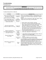
Страница 46: ... to Central heat off DHW demand or Central Heat Optional Priority This has been set to allow all of the heat to be provided for fast indirect water heater recovery After priority protection time or the end of the Domestic Hot Water Heat Request the system and boiler pumps will be free to run Display Completely Dark Fan off LWCO lights off no green power light on Control No 120Vac Power at Boiler C...

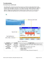
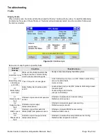
Страница 47: ...an also silence an audible alarm generated by the control during a lockout or alert by alarm condition Figure 21 General Alarms Indication Condition Possible Cause Blank Screen with no control icon shown Display lost communication with control Failure to establish Communication upon display boot up once you establish communication reboot display to read controller and setup display properly Gray C...

Страница 48: ...ry other kind of problem that isn t a lockout or hold is an alert Examples include boiler control abnormal holds LL master problems faults from non safety functions etc Alerts never require manual intervention to reset them that is if the alert clears up then normal operation will continue An alert is not a condition it is an event The cause of the alert may be a condition e g something that is ca...

Страница 49: ... move the view left and right to show all analog I O status Each Sensor is provided with the following diagnostic information Indication Possible Cause Open Check sensor wiring Sensor open will show if the sensor has not yet been wired to the boiler or if a wire is loose Shorted Check sensor wiring Sensor terminals are connected to each other of the sensor has failed Outside low range Outside high...

Страница 50: ...F all other contacts below or downstream that limit will also show as OFF When troubleshooting the first Limit in the string of OFF Limits is the contact to inspect ON limits indicating the limits are closed Figure 23 Limit String Status OFF limits indicating the limits are open In this case the contact at A6 ILK Thermal Fuse Limit is open The status of limits downstream is unknown NOTE Some Limit...

Страница 51: ...is not energized Limit Control Input LCI is not ON Refer to limit string screen for list of limits A wire is loose 67 Boiler Safety Limit Open Boiler Safety Limit Interlock ILK is OFF Lockout input ILK is not ON Refer to limit string screen for list of limits Loose wiring to limit device Jumper not installed 91 Return sensor fault Shorted or open return temperature sensor Shorted or miswired retur...

Страница 52: ...Verify that system is purged of air and that appropriate valves are open Sensor wiring reversed Supply or return sensor defective 88 Supply temp has risen too quickly Supply water temperature has risen too quickly See possible causes for Hard Lockout 4 Inadequate boiler water flow Verify that circulator is operating and that circulator and piping are sized per Installation Instructions Manual Wate...

Страница 53: ... wire is loose Ground in one of the wires 79 Supply high limit Supply sensor detected temperatures exceeding High Limit Heating load at time of error was far below the minimum firing rate of the boiler Defective system circulator or no flow in primary loop Defective boiler circulator no flow or insufficient flow in boiler loop Control system miswired so that the boiler operation is permitted when ...

Страница 54: ...Control Safety related parameter detected See display for details Safety Parameter verification required Contact factory 50 Invalid Modulation Parameter Unacceptable Control Modulation related parameter detected Reset the control 2 Safety data verification needed Safety related parameter change has been detected and verification has not been completed Safety related Control parameter has been chan...

Страница 55: ...o check speed 68 ILK ON This lockout occurs when the interlock string is closed before the blower starts The airflow switch is the only device in the interlock string that will open when in standby Air pressure in the boiler room has become negative Excessive downdraft in the stack Blower is spinning before being commanded by the hydronic control Make sure blower is not running in standby Airflow ...

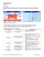
Страница 56: ...ith technical support Figure 26 Lockout History View Lockout History Lockout History is stored in a first in first out basis Each lockout file is stored with boiler run hour of when the lockout occurred status at the time of the lockout and the Annunciator in the limit string that caused the lockout Only if applicable to that lockout Up to 15 lockouts may be stored in the Lockout History 1 being t...

Страница 57: ...rts include any problem that is NOT a Lockout or Hold The alerts are recorded in a list with the most recent appearing at the top The alarm list can be scrolled through The alerts are given a date and time stamp which allows for better troubleshooting capability Touching the alert shows more information about the alert that occurred Figure 28 Alert Log Screens ...

Страница 58: ...Right Click on the Removable Disk and select Format Select File system FAT32 Select Start and then select OK to format the USB Thumb Drive The USB Thumb Drive is now FAT32 format Save Screenshot to USB Pressing the icon on any screen will save a screenshot to the display memory Up to 16 screen shots can be saved on the display at one time To transfer the screenshots to a USB thumb drive take the f...

Страница 59: ...zel 9 7 16 x 6 21 32 x 1 27 32 Panel Cutout 8 x 5 1 2 Electrical Ratings Input voltage 24 Vac 25 25 Input Current 500 mA max Power Consumption 12W Backup Battery 3V Lithium Battery CR2032 about 3 years operating life with power removed Battery used to maintain time and date clock not display memory Operating Temperature 4ºF 158ºF 20ºC 70ºC Storage Shipping Temperature 22 F 176ºF 30ºC 80ºC Humidity...

Страница 60: ...lement two wire thermistor type temperature sensor 6 inch lead wires female Molex 0039013029 quick connector 3 8 inch diameter 101935 01 Direct Immersion Type DHW Sensor Header Sensor 10K ohm single element two wire thermistor type Direct Immersion temperature sensor Insertion is NPT 105685 01 Thermowell Type DHW Sensor Header Sensor 10K ohm single element two wire thermistor type temperature sens...

Страница 61: ...odbus Supervisor 32 OUTDOOR RESET CONFIGURATION Outdoor Reset Enable Disable Enable Disable Basic 33 Minimum Outdoor Temperature 50 to 32 F Basic 33 Maximum Outdoor Temperature 35 to 100 F Basic 33 Low Water Temperature 70 to 180 F Basic 33 Minimum Boiler Water Temperature 50 to 185 F Basic 33 Boost Time 0 to 30 minutes Basic 34 Central Heat ODR Max Off Point 50 to 190 F Basic 34 DOMESTIC HOT WATE...

Страница 62: ... Rate to 0 10V Supervisor 37 Analog Input Hysteresis 0 to 10 tenths Supervisor 37 Analog Output Hysteresis 0 to 40 tenths Supervisor 37 PUMP CONFIGURATION Contact A CH Pump Never Any Demand Central Heat No Priority Central Heat Optional Priority DHW Pump Supervisor 38 Contact B Boiler Pump Never Any Demand Supervisor 38 Contact C DHW Pump Never Isolation Valve DHW Pump Supervisor 38 Overrun Time C...

Страница 63: ...ONFIGURATION Master Enable Disable Enable Disable Supervisor 42 Lead Lag Setpoint Source Local 4 20mA Modbus Supervisor 42 LL Demand Switch STAT terminal Modbus STAT Supervisor 42 LL DHW Demand Switch Disable DHW Sensor Shorted Supervisor 42 DHW Two Boiler Start Enable Disable Supervisor 42 Add Stage Detection Time 0 5 to 20 minutes Supervisor 42 Drop Stage Detection Time 0 5 to 5 minutes Supervis...

Страница 64: ...Boiler Control Instruction Operation Manual Rev 1 Page 63 of 64 Notes ...

Страница 65: ...Boiler Control Instruction Operation Manual Rev 1 Page 64 of 64 Notes ...

Страница 66: ...and must be affixed near the boiler for future reference TO THE OWNER This boiler should be inspected annually by a Qualified Service Agency PFC8202 R1 09 22 1C Printed in U S A 2022 PB Heat LLC All rights reserved PB HEAT LLC 131 S CHURCH STREET BALLY PA 19503 PFC 2000 PFC 2500 PFC 3000 PFC 3500 PFC 4000 PureFire ...

Отзывы: