


Boiler Control Instruction & Operation Manual, Rev 1
Page
19
of 64
Installation
Terminal Layout
A
B
C
A
B
C
Boiler to Boiler
Sequence Master
Communication
MB1
MB2
From Control
J3 Terminal
2
3
4
10
9
8
60
59
58
57
56
55
2
3
1
4
5
RJ45 Port
Connects to
Up to 8 boilers
Connection to
Protonode
Factory Supplied
P26
P21
P27
N
To Energy Management
System (EMS)
RS485 Modbus
Communication
To Energy Management
System (EMS)
BACnet MSTP, Metasys N2,
Or LonWorks
Communication
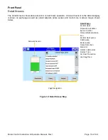
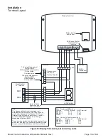
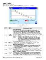
Note
The Sequence Master communicates to all
networked boilers using the MB2 Connection on
each boiler. Separately the Display COM 3 port
(Internal System Menu) on each boiler is used to
communicate RS485 Modbus to the Energy
Management System (EMS).
These communications are electrically separate from
each other and make the connection between boilers
using a common RJ45 Module and Ethernet Cable.
Note - Display to EMS wiring;
Function
COM 2 Terminal
RJ45 Terminal
RS485 (+)
Pin 4 -
Pin 1
RS485 (-)
Pin 5 -
Pin 3
Ground
Pin 6 -
Pin 2
Note - Control to Peer-to-peer wiring;
Function
J3 Terminal
RJ45 Terminal
RS485 (+)
MB2 A
-
Pin 8
RS485 (-)
MB2 B
-
Pin 7
Ground
MB2 C
-
Pin 2
PCB-06
COM1
COM2
24 VAC
A
B
C
A
B
C COM PWR
24VAC
Transformer
N +24V
USB Connection for
Historical Data
Collection
Battery located
behind door
Display Rear View
Figure 14: Display Terminal Layout and wiring notes