


Boiler Control Instruction & Operation Manual, Rev 1
Page
32
of 64
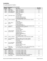
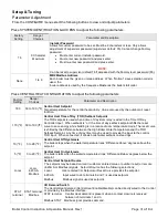
Setup & Tuning
Parameter Adjustment
Table 11:
Response Speed Adjustment Guidelines
Central Heat Continued
Factory
Setting
Range /
Choices
Parameter and Description
130 F
50
– 185 F
Central Heat 4-20mAdc Setup, 4 mA Water Temperature
Sets the Central Heat Temperature Setpoint corresponding to 4 mA.
180 F
50
– 185 F
Central Heat 4-20mAdc Setup 20 mA Water Temperature
Sets the Central Heat Temperature Setpoint corresponding to 20mA.
44
0 to 400
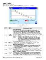
Central Heat P Gain
Proportional Gain value for Sequencer control modes. A larger gain value results in
tighter, more active, PID control. Gain is the primary PID modulation rate tuning
adjustment and provides the immediate modulation rate response. Pick a gain based
on the desired initial response. The burner modulation rate can oscillate if the
Proportional Gain is too large.
45
0 to 400
Central Heat I Gain
Integral gain value For Central Heat control Modes. A larger value makes the Integral
ramp in less time (i.e., faster). Integral is a secondary PID modulation rate tuning
adjustment that ramps the output over time (typically minutes). Based on the selected
Local PID P, select the corresponding (from above table) Integral value. Repeats per
minute between 0.5 and 2.0 are typical. The burner modulation rate can oscillate if
the Integral time is too large.
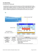
Outlet
Sensor
Outlet Sensor,
S5 (J8-11)
Sensor
Central Heat Modulation Sensor
Heat Demand may respond to the boiler
’s Supply Temperature or S5 (Header)
Temperature sensors. When Header Sensor is selected the boiler is fired in response
to the sensor wired to Header Sensor terminal J8 terminals 11 and 12.
NOTE
: Outdoor air sensor cannot be selected to use the same terminal.
Local
Local,
4-20mA,
Modbus
Modulation Source
The boiler can modulate (vary boiler heat input) based on local or remote (4-20mA or
Modbus) signals. Modulation begins after the start sequence finishes and the boiler is
released to modulate. Modulation Source has the following selections:
Local Local setpoint and control is used to create firing rate.
4-20mA
Input wired to J8 terminals 6 and 7 is used as modulation rate.
Modbus
Modbus signal is used as modulation rate.