PedigreeTechnologies.com | Support: (701)-499-0022
8
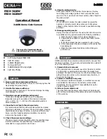
STEP FOUR
Plug the 16 pin plug from the short end of the
APMM harness into the LMU DIAG port on the
power module.
STEP FIVE
Plug the 6 pin plug from the APMM harness into
the AUX 1 port on the power module.
STEP SIX
Plug the diagnostic cable
(from STEP ONE)
into the
VEHICLE DIAG. port on the power module.
STEP SEVEN
Plug the usb adapter cable into the 10 pin port on
the side of the power module.
APMM Power Module Installation
- CalAmp LMU 3640
continued...
APMM Harness
Power Module
Diagnostic Cable
Power Module
Camera Power
Cable
For a previously installed camera, remove the power
cable of the old camera and replace with the 10 pin
connector of the new camera power/accessory
harness.
CameraView
Mitac