GRL-PCIE5-CEM-RXA User Guide and MOI
Rev7.0
© Granite River Labs 2022 Version 7.0, June 2022. Updated 06.29.2022
Page 84 of 123
8.
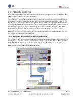
Using phase matched cables, connect Channels 1 and 3 on the oscilloscope to the pick-off tee
tapped input ports.
9.
Using coaxial cables, connect the pick-off tee outputs to the PCIe5 Re-Driver and then to the
MU195040A data inputs for loopback error detection.
10.
Using the J1627A GND connection cable, connect the CLB to ground.
8.2.3
Initial Tx EQ Startup and Testing
Prior to starting this test, take note of the following:
▪
This test uses AC fit methodology defined in the
PCIe CEM 5.0 Specification
for preset testing
at 32 GT/s. Testing at lower data rates uses Vb based methodology defined in respective
PCIe
Base Specifications
.
▪
To account for measurement noise, a tolerance of ±1.0 dB is used for measured preshoot and
de-emphasis that are defined as 0.0 dB in the
PCI Express Base Specification
.
▪
Due to measurement sensitivity having more impact on higher boost preset, a tolerance of
±1.5 dB is used for P10 preshoot.
▪
The designs are expected to not support any preshoot or de-emphasis on presets that define
0.0 dB for preshoot or de-emphasis. The allowed tolerance is to account for measurement
noise only.
The Anritsu MX183000A High-Speed Serial Data test software is used with the MX190000A test
application on the MP1900A BERT to perform the initial Tx EQ test. The oscilloscope will also be
used to capture waveforms for post processing analysis.
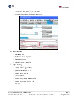
1.
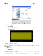
Configure the oscilloscope as follows:
•
Averaging: OFF
•
Horizontal Scale: 6.25 µs/div (2M UI)
•
Max Bandwidth: 33 GHz
•
Sampling Rate: ≥ 128 GS/s
•
Trigger: 0 V, Channel 1
2.
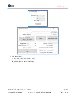
Set Preset 0 on the BERT.
3.
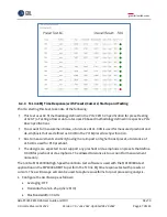
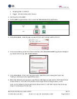
On the
BERT’s Applications screen, select the MX183000A
Utility application.


