
GRL-PCIE5-CEM-RXA User Guide and MOI
Rev7.0
© Granite River Labs 2022 Version 7.0, June 2022. Updated 06.29.2022
Page 60 of 123
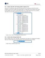
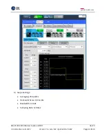
8.1.4
Amplitude, Preset, SJ and RJ Calibration Setup
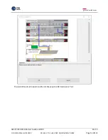
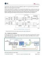
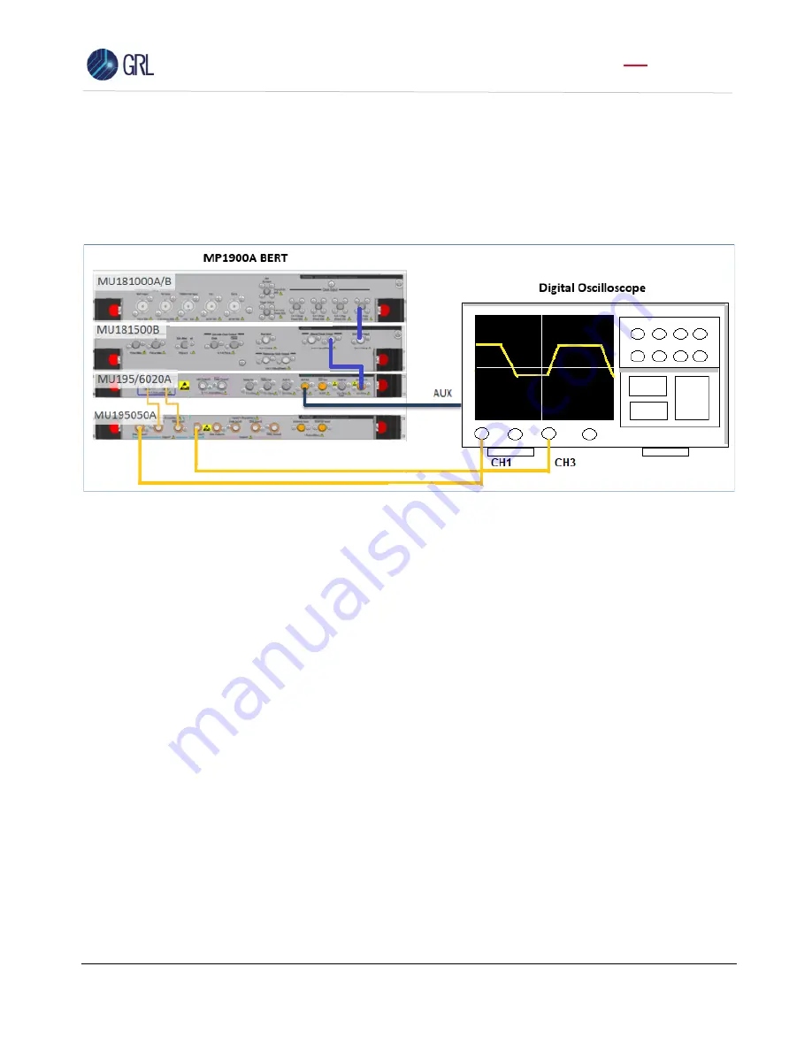
The following connection diagram shows the calibration setup for amplitude, preset, SJ, and RJ at
TP3 without any channel effect. The MP1900A BERT is directly connected to a digital oscilloscope
supporting
≥ 50 GHz bandwidth and ≥ 128 GS/
s sampling rate.
F
IGURE
50.
C
ONNECTION
D
IAGRAM FOR
A
MPLITUDE
,
P
RESET
,
SJ
AND
RJ
C
ALIBRATION
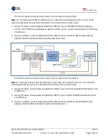
1.
Using a SMA-SMA short cable, connect the MU181000A/B clock output to the MU181500B Ext
clock input.
2.
Using a SMA-SMA short cable, connect the MU181500B jittered clock output to the
MU195020A/MU196020A Ext clock input.
3.
Using coaxial cables, connect the MU195020A/MU196020A data outputs to the MU195050A
data inputs.
4.
Using coaxial cables, connect the MU195050A data outputs to the digital Scope channels.
5.
Using a SMA cable, connect the MU195020A/MU196020A Aux output to the digital Scope for
pattern sync triggering.
8.1.5
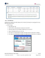
Anritsu Standard BERT Device Test Application (MX190000A) Startup
To adjust the calibration parameters when measuring on the Scope, use the MX190000A Standard
test application on the MP1900A BERT.
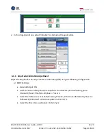
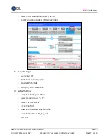
1.
On the BERT’s Applications screen,
select the MX190000A Standard Bert application for SI (if
using SI-PPG) or Standard Bert application for SI and PAM4 (if using PAM4-PPG).


