b) This menu is displayed when the data format is asynchronous:
2. Data Format
Select Option 2 in the SOFTWARE CONFIGURATION Menu to
select the async or sync data format (See below). This option controls
whether the unit operates in asynchronous or asynchronous data
formats.
3. Clock Mode
Select Option 3 in the SOFTWARE CONFIGURATION Menu to
select the sync clock mode (See below).
Set this option as follows:
Master Clock - Internal
: Selection 1 allows the Model
1092RC to generate an internal clock as the timing source.
Master Clock - External
: Selection 2 allows the Model
1092RC to Derive the system clock from the locally connected
DTE.
Slaved to Receive Clock:
Selection 3 to allows the Model
1092RC to derive the timing source from the incoming data
stream from the remote Model 1092RC.
14
SGND & FRGND (JB4)
In the connected position, this strap links DB-25 pin 7 (Signal
Ground) and frame ground. In the open position, pin 1 is disconnected
from frame ground.
JB4
Position 1&2 = SGND (Pin 7) and FRGND Connected
Position 2&3 = SGND (Pin 7) and FRGND Not Connected
3.3.2 Model 1000RCM13492 Strap Settings
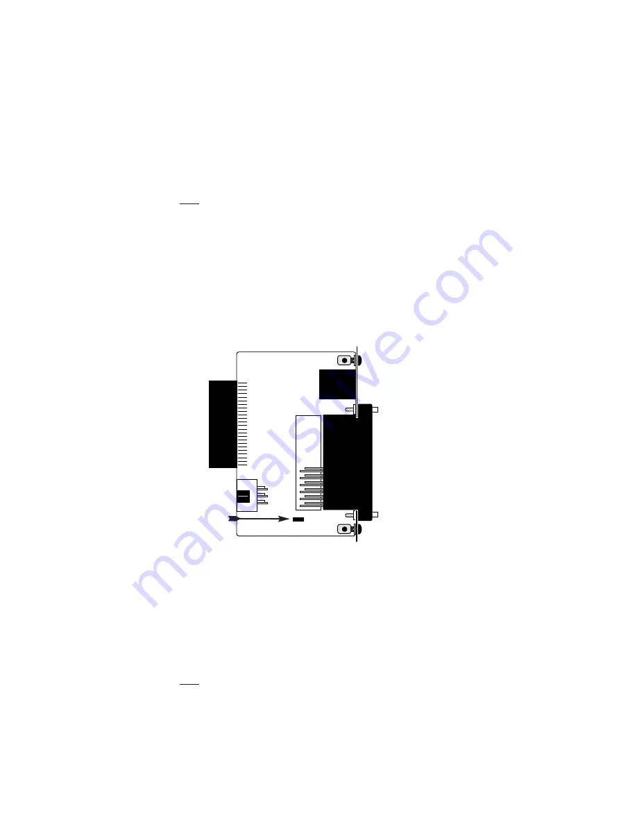
Figure 7 shows the strap location for the Model 1000RCM13492
(M/34/RJ-45) rear card. This strap determines whether Signal Ground
and Frame Ground will be connected.
SGND & FRGND (JB4)
In the connected position, this strap links Signal Ground and frame
ground. In the open position, signal ground is disconnected from frame
ground.
JB4
Position 1&2 = SGND and FRGND Connected
Position 2&3 = SGND and FRGND Not Connected
23
Figure 7.
M/34/RJ-45 strap locations
JB4
123
Содержание 1092RC
Страница 3: ......
Страница 5: ......
Страница 7: ......
Страница 9: ......
Страница 11: ......
Страница 13: ......
Страница 15: ......
Страница 17: ......
Страница 19: ......
Страница 21: ......
Страница 23: ......
Страница 25: ......
Страница 27: ......
Страница 29: ......
Страница 31: ......
Страница 33: ......
Страница 35: ......
Страница 37: ......
Страница 39: ......
Страница 40: ......


