


21
3.6.8 Explosion Vent installation
3.6.8.1 Introduction
Your Parker Dust-Hog® supplied with an explosion vent is
designed to minimize structural damage in the event of an explo-
sion. It does not prevent explosions!
The responsible user should:
1. Take every possible precaution to prevent a fire or explosion
from occurring
2. Consult with their insurance carrier or local authorities regarding
the hazardous nature of dust produced by them.
3. Consult and comply with national and local codes or bulletins
when determining location and operation of the dust collector.
4. Do not exceed negative operating pressure of the unit.
5. Do not exceed operating temperature of the dust collector (not
to exceed 180°F (82°C)).
3.6.8.2 Operating & Precautions
1. Install unit with the explosion vent directed away from occu-
pied areas.
2. When the explosion vent is properly installed, the rating tag
and caution stickers should be in plain sight for all to see. If
the explosion vent is installed incorrectly, damage could occur
to the explosion vent and to the operator or plant equipment.
3. Ductwork added to the explosion vent flange may create a
secondary hazard. User must comply with NFPA standard 68,
and/or other codes that apply.
4. Do not place hands or any other objects in vent opening.
Serious injury or damage to plant equipment could occur.
5. If any leakage occurs, shut down unit and contact Parker
immediately.
6. Never inspect explosion vent(s) with unit running.
7. Only use explosion vent supplied by Parker.
8. Any vent installed, which has been provided by someone other
than Parker will void all warranties on the dust-collector.
In case of explosion, contact Parker immediately.
Do not operate or rearm the collector with another
explosion vent without contacting Parker first.
Serious injury could occur.
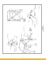
3.6.8.3 Unit Set-Up
The normal shipping routine for an assembled SFC unit is with an
enclosed box truck. This type of truck will not be able to trans-
port an assembled 4-high unit due to height restrictions within
the vehicle. When shipping this unit, it will be necessary to ship
the top panel and explosion vent separately. This will require the
customer to assemble this to the unit on site. Refer to Figure 14
for assembly details.
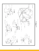
3.6.9 Extended Dirty Air Plenum (EDAP) For 5 High SFC Unit
The normal shipping routine for an assembled SFC unit is with an
enclosed box truck. This type of truck will not be able to transport
an assembled 5-high unit due to height restrictions within the
vehicle. When shipping this unit, it will be necessary to ship the
EDAP separately. This will require the customer to assemble this
to the unit on site. Refer to Figures 15 & 16 for assembly details.
3.6.10 Sprinkler Coupler
CAUTION: Water sprinkler systems can deliver high volumes of
water when activated and in turn can fill up the dust collector,
collect in particulate collection drums and saturate filter car-
tridges. Large amounts of water inside the dust collector can
and will add excess weight to the structure including stress to
the support and extension legs resulting in possible failure or
collapse. Adequate drainage should be a part of any dust col-
lector with water sprinkler options.
3.6.10.1 Sprinkler Coupler
Optional sprinkler couplers are provided on the SFC unit for the
convenience of fire control system professionals. The buyer or
owner/user is responsible to supply, install and test the sprinkler
head and any related or required fire control system devices,
components or accessories. It is the responsibility of the buyer
or owner/user to test functionality and operation of the fire
control system for water leakage, correct installation, appropri-
ate fire control system component location, correct operation
and appropriate application while strictly adhering to any and
all prescribed AHJ, OSHA, NFPA, Federal, State/Provincial and
Local codes, standards, regulations and instructions appli-
cable to industrial dust collectors, fire control systems and any
related and required components and processes.
3.6.10.2 Sprinkler Head
If a sprinkler head is requested to be installed at the factory, it is
the sole responsibility of the buyer or owner/user to supply the
applicable and desired sprinkler head device or sprinkler head
specification including manufacturer and part number and any
special installation instructions. It is also the responsibility of the
buyer or owner/user to test functionality and operation of the
sprinkler head and the fire control system for water leakage,
correct installation, appropriate fire control system component
location, correct operation and appropriate application while
strictly adhering to any and all prescribed AHJ, OSHA, NFPA,
Federal, State/Provincial and Local codes, standards, regula-
tions and instructions applicable to industrial dust collectors,
fire control systems and any related and required components
and processes.
4. Operation
Shut off unit disconnect and lock out all electrical power
to the dust collector prior to performing service work.
!
D A N G E R
!
D A N G E R
Содержание SFC
Страница 1: ...Downward Flow Cartridge Dust Collector Owner s Manual Model SFC...
Страница 7: ...v Page intentionally left blank...
Страница 11: ...4 FIGURE 2 SFC Typical SINGLE UNIT Installation Diagram PARKER PARKER 44 10335 0001...
Страница 12: ...5 FIGURE 3 Recommended Unit Clearances 44 10337 0001...
Страница 14: ...7 FIGURE 4 Single Hopper SFC 44 10309 0001...
Страница 15: ...8 FIGURE 5 Multiple Hopper SFC 44 10309 0002...
Страница 16: ...9 FIGURE 6 Multiple Hopper SFC 44 10309 0003...
Страница 17: ...10 FIGURE 7 Multiple Modules SFC 44 10310 0001...
Страница 19: ...12 FIGURE 8 SFC Pressure Gauge Installation 44 10333 0001 Rev A...
Страница 20: ...13 FIGURE 9 Solenoid Wiring to Pulse Controls for 2 3 4 and 5 Tier Units...
Страница 21: ...14 FIGURE 10 Pneumatic Valve Assembly 44 10332 0001...
Страница 24: ...17 FIGURE 12 Abrasive Inlet Installation 44 10338 0001...
Страница 27: ...20 FIGURE 16 EDAP Interconnection FIGURE 15 EDAP Installation 48 10007...
Страница 30: ...23 FIGURE 17 SFC Series Door Filter Installation 44 10329 0001...
Страница 37: ...30 7 Illustrated Parts FIGURE 21 SFC Series 44 10330 0001 FIGURE 22 SFC Series Explosion Vents...
Страница 39: ...32 Page intentionally left blank...


