


KNOW YOUR EQUIPMENT
READ THIS MANUAL FIRST.
Your SFC system should provide many years of trouble-free service. This manual will
help you understand the operation of your SFC unit. It will also help you understand
how to maintain it in order to achieve top performance. For quick future reference, fill in
the system and filter information in the spaces below. Should you need assistance, call
the Parker customer service number shown below. To expedite your service, have the fol-
lowing information available when contacting Parker.
Parker Order #: ________________________________________________________________
Unit Model #: __________________________________________________________________
Unit Serial #:___________________________________________________________________
Cartridge Filter Part #: __________________________________________________________
System Accessories:
______________________________________________________________________________
______________________________________________________________________________
______________________________________________________________________________
Installation Date: _______________________________________________________________
Parker Hannifin Customer Service
1-800-343-4048
Содержание SFC
Страница 1: ...Downward Flow Cartridge Dust Collector Owner s Manual Model SFC...
Страница 7: ...v Page intentionally left blank...
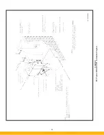
Страница 11: ...4 FIGURE 2 SFC Typical SINGLE UNIT Installation Diagram PARKER PARKER 44 10335 0001...
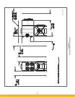
Страница 12: ...5 FIGURE 3 Recommended Unit Clearances 44 10337 0001...
Страница 14: ...7 FIGURE 4 Single Hopper SFC 44 10309 0001...
Страница 15: ...8 FIGURE 5 Multiple Hopper SFC 44 10309 0002...
Страница 16: ...9 FIGURE 6 Multiple Hopper SFC 44 10309 0003...
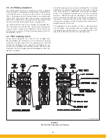
Страница 17: ...10 FIGURE 7 Multiple Modules SFC 44 10310 0001...
Страница 19: ...12 FIGURE 8 SFC Pressure Gauge Installation 44 10333 0001 Rev A...
Страница 20: ...13 FIGURE 9 Solenoid Wiring to Pulse Controls for 2 3 4 and 5 Tier Units...
Страница 21: ...14 FIGURE 10 Pneumatic Valve Assembly 44 10332 0001...
Страница 24: ...17 FIGURE 12 Abrasive Inlet Installation 44 10338 0001...
Страница 27: ...20 FIGURE 16 EDAP Interconnection FIGURE 15 EDAP Installation 48 10007...
Страница 30: ...23 FIGURE 17 SFC Series Door Filter Installation 44 10329 0001...
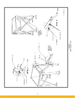
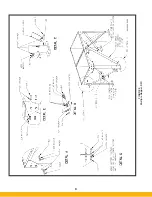
Страница 37: ...30 7 Illustrated Parts FIGURE 21 SFC Series 44 10330 0001 FIGURE 22 SFC Series Explosion Vents...
Страница 39: ...32 Page intentionally left blank...


