


15
3.4.3 Heater Wiring
In cold or damp environments, the heater serves to prevent the
electric solenoid valves from freezing due to cold temperatures
or condensation. If optional solenoid valve heater is purchased,
each 4 solenoid valve enclosures will contain a 70-watt car-
tridge heater, 6, 8 and 10 solenoid valve enclosures will contain
a 120-watt cartridge heater internally prewired to a thermostat.
The customer must provide a 100-130VAC, 50/60Hz, 1 amp
power to the heater circuit for each module. The power must be
available to the module solenoid valve enclosure(s) at all times
(even when the blower is shut down) to ensure temperature
regulation inside each solenoid valve enclosure is continual.
When multiple module solenoid valve enclosures with heaters
are installed, daisy chain the wiring so that each heater will have
100/115VAC, 50/60 Hz at all times. Make certain enough cur-
rent is available to supply all heaters.
Example: If three solenoid valve enclosures are supplied with car-
tridge heaters, make certain the voltage supply can deliver 3
amps (1amp per heater).
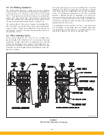
3.5 Compressed Air Connection
Do not allow water and/or oil from the compressed
air system into the compressed air manifold reservoir.
To ensure a clean, dry air supply, especially when the
unit is installed outdoors, a water filter with automatic
drain and a coalescing filter should be installed (refer
to Figure 10).
Clean, dry, 90-110 PSIG (6.2-7.6 BAR) compressed air is required
for the pulse cleaning system to function properly. Compressed
air consumption is noted on the Parker sales drawing. A shut-off
valve, pressure regulator and pressure gauge should be installed
close to the SFC unit. Parker recommends dedicated oil and water
removal filters be used to ensure clean, dry air is delivered to the
pulse system. Contact your local SFC representative for informa-
tion about Parker’s Pneumatic Valve Assembly. Refer to Figure 10
for recommended compressed air piping and Table 1 below for
proper compressed air line sizing.
NOTE: Using Table 1, select the proper diameter compressed air
line pipe to supply your dust collector. The final connection
size is a female 1” NPT fitting on each module.
NOTE: Purge the compressed air line to remove any debris prior
to making the final connection to the SFC compressed air
manifold(s). Apply pipe fitting sealant on all compressed air
supply pipe fittings and connections.
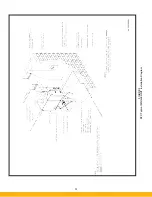
3.6 Assembly of Optional Equipment
3.6.1 Blower Purge Package Installation
TIP OVER HAZARD
Anchor dust collector to concrete pad prior to install-
ing blower assembly. Make certain all hardware is
properly tightened.
If a top-mount blower package was ordered, read the manu-
facturer’s Installation and Operation Manual completely before
installing the blower. The blower Installation and Operation
Manual is attached to the fan package. Perform all pre-installa-
tion checks prior to installing the blower.
TIP OVER HAZARD
If blower package has a 20 HP (15 kW) motor or larger,
ensure the blower support legs are installed beneath
the clean air plenum of the module to which the blower
will be mounted.
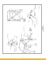
For top-mount blower packages of 20 HP (15 kW) or larger, an
additional set of support legs is provided. The additional support
legs must be mounted under the filter module supporting the blower
package (refer to Figure 11). Bolt the mounting plate to the bottom
of the appropriate clean air plenum with the hardware provided.
Bolt the leg assemblies to the mounting plate with the hardware
provided. Secure leg assemblies to the concrete mounting pad with
appropriate anchoring hardware.
Remove the clean air plenum cover plate on top of the filter module
and save the mounting hardware. Ensure ribbon gasket remains on
the unit. Lift blower package using safe, suitable means and position
blower base holes over filter module holes with blower discharge
pointing in the desired direction. Secure with bolt/washer assem-
blies previously removed. Top-mount blower packages include a
blower outlet damper. Install blower damper to outlet of blower
assembly with hardware provided.
If the blower package is a ground-mount blower, read the manu-
facturer’s Installation and Operation Manual completely before
installing the blower. The blower Installation and Operation Manual
is attached to the fan package. Perform all pre-installation checks
prior to installing the blower.
Outlet ducting from the SFC unit to the blower package can be con-
nected to either the top or bottom clean air section access panel(s).
It is recommended industry practice to provide vibration isolation
between the blower inlet and the dust collector outlet ducting.
!
D A N G E R
!
D A N G E R
Pipe Diameter
1 inch (25mm)
1-1/2 inch (38mm)
2 inch (51mm)
Number
of Filter
Section
Modules
1-3
3-5
+5
or
Distance of Supply Air
Piping Run From Main
Compressor Line
50 feet (15 meters)
100 feet (31 meters)
+100 feet (+31 meters)
Table 1
CAUTION
Содержание SFC
Страница 1: ...Downward Flow Cartridge Dust Collector Owner s Manual Model SFC...
Страница 7: ...v Page intentionally left blank...
Страница 11: ...4 FIGURE 2 SFC Typical SINGLE UNIT Installation Diagram PARKER PARKER 44 10335 0001...
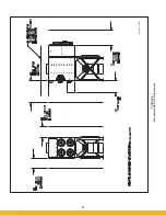
Страница 12: ...5 FIGURE 3 Recommended Unit Clearances 44 10337 0001...
Страница 14: ...7 FIGURE 4 Single Hopper SFC 44 10309 0001...
Страница 15: ...8 FIGURE 5 Multiple Hopper SFC 44 10309 0002...
Страница 16: ...9 FIGURE 6 Multiple Hopper SFC 44 10309 0003...
Страница 17: ...10 FIGURE 7 Multiple Modules SFC 44 10310 0001...
Страница 19: ...12 FIGURE 8 SFC Pressure Gauge Installation 44 10333 0001 Rev A...
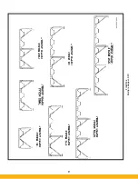
Страница 20: ...13 FIGURE 9 Solenoid Wiring to Pulse Controls for 2 3 4 and 5 Tier Units...
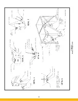
Страница 21: ...14 FIGURE 10 Pneumatic Valve Assembly 44 10332 0001...
Страница 24: ...17 FIGURE 12 Abrasive Inlet Installation 44 10338 0001...
Страница 27: ...20 FIGURE 16 EDAP Interconnection FIGURE 15 EDAP Installation 48 10007...
Страница 30: ...23 FIGURE 17 SFC Series Door Filter Installation 44 10329 0001...
Страница 37: ...30 7 Illustrated Parts FIGURE 21 SFC Series 44 10330 0001 FIGURE 22 SFC Series Explosion Vents...
Страница 39: ...32 Page intentionally left blank...