19
If a drum lid quick release clamp was ordered, use its clamping
mechanism to secure the drum lid and drum. To install the clamp:
Before placing the drum lid into place, open the clamp and slide it
around the drum. Once the clamp is around the drum, install the
drum lid on top of the drum. After the drum lid is in place, slide the
clamp up and around the lip of the drum lid and drum. Once the
clamp is around the lip of the drum, pull the clamp close to secure
the drum lid.
If a slide gate was ordered, it was factory installed on the hopper.
Open the slide gate. Repeat for multiple drum lid connections.
NOTE:
The hopper(s) is not designed for dust storage.
The slide gate should remain open during normal operation.
3.6.6 Inlet Cover and Blank Cover Plate Installation
Inlet collar and blank cover plates bolt directly to the SFC unit. Inlet
and outlet collar assemblies are specified with initial order; the dust
collector is supplied with all blank cover plates.
3.6.7 Remote Blower Start/Stop Assembly
A remote blower start/stop push button station is available for field
installation with SFC systems supplied with a Parker combination
magnetic motor/blower starter panel. The customer is required
to supply interconnecting field wiring and mounting hardware for
remote blower start/stop push button station installation. Refer to
the DPM/DPC Installation and Operation Manual.
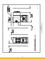
FIGURE 14
SFC Explosion Vent Installation (Top Mount)
44-10365-0001
Содержание SFC
Страница 1: ...Downward Flow Cartridge Dust Collector Owner s Manual Model SFC...
Страница 7: ...v Page intentionally left blank...
Страница 11: ...4 FIGURE 2 SFC Typical SINGLE UNIT Installation Diagram PARKER PARKER 44 10335 0001...
Страница 12: ...5 FIGURE 3 Recommended Unit Clearances 44 10337 0001...
Страница 14: ...7 FIGURE 4 Single Hopper SFC 44 10309 0001...
Страница 15: ...8 FIGURE 5 Multiple Hopper SFC 44 10309 0002...
Страница 16: ...9 FIGURE 6 Multiple Hopper SFC 44 10309 0003...
Страница 17: ...10 FIGURE 7 Multiple Modules SFC 44 10310 0001...
Страница 19: ...12 FIGURE 8 SFC Pressure Gauge Installation 44 10333 0001 Rev A...
Страница 20: ...13 FIGURE 9 Solenoid Wiring to Pulse Controls for 2 3 4 and 5 Tier Units...
Страница 21: ...14 FIGURE 10 Pneumatic Valve Assembly 44 10332 0001...
Страница 24: ...17 FIGURE 12 Abrasive Inlet Installation 44 10338 0001...
Страница 27: ...20 FIGURE 16 EDAP Interconnection FIGURE 15 EDAP Installation 48 10007...
Страница 30: ...23 FIGURE 17 SFC Series Door Filter Installation 44 10329 0001...
Страница 37: ...30 7 Illustrated Parts FIGURE 21 SFC Series 44 10330 0001 FIGURE 22 SFC Series Explosion Vents...
Страница 39: ...32 Page intentionally left blank...


