3
TIP OVER HAZARD
The SFC dust collector should be mounted on a solid,
level, reinforced concrete foundation. Other mounting
options are also possible. Structural calculations for
the foundation or other mounting arrangements
must include the weight of the collected material
and the weight of all auxiliary equipment installed
with the dust collector (ducting, abrasive inlet,
blower package, afterfilter assembly, etc.). These
weights must be considered together with wind
loading, seismic loading and other live load ratings
when designing the dust collector foundation sup-
port structure. Consult a professional engineer when
designing the foundation for the unit.
The system should be designed with the ability to regulate airflow.
Two common ways to do this are through the use of flow/volume
control dampers or variable frequency drives to control the speed
of the fan motor. Parker offers both of these options. If flow con-
trol dampers are selected, the interconnecting duct work should
be designed to account for the installation of said damper. These
dampers can be installed on the inlet or outlet ducting of the SFC
unit. Whether you control the flow through the use of a damper
or VFD, the ductwork must be properly sized to meet the recom-
mended air velocities for the material being collected.
Follow ducting design methods as listed in the Industrial Ventilation
Manual as recommended by the American Conference of
Governmental Industrial Hygienists.
3.3 Assembly Of Standard Equation
CRUSH AND ELECTROCUTION HAZARD
Use adequate safety measures when lifting and
assembling any heavy components. Consult your
plant safety personnel for recommendations.
In preparing to attach the filter module to the hopper,
connect lifting slings and spreader bars to all filter
module lifting lugs with clevis pins. Use spreader
bars to distribute the load evenly. Location must
be clear of all obstructions, such as utility lines or roof
overhangs.
Remove all crating, strapping and hold-down bolts. Locate all
hardware bags, sealant and other assembly materials provided
with your unit.
3. Installation
3.1 Off Loading and Inspection
SFC dust collector modules are shipped assembled (with car-
tridges installed) on skid(s). Other skids will contain the hopper/
leg assembly and other components. Other accessories (afterfilter
assemblies, blower packages, dust storage drums, silencers,
etc.) may be on additional, separate skids.
TIP OVER HAZARD
Lift the dust collector components by the packing skids
or use the external lifting lugs provided on the filter
module. Do not lift the filter module of the dust collec-
tor by placing lift truck forks through the cartridge filter
access doors. The filter support rails or venturi installed
on the tubesheet could be damaged.
Upon receipt of your unit, check for any shipping damage.
A damaged carton indicates that the equipment may have
received rough handling during shipping that may have caused pos-
sible internal damage. Notify your delivery carrier and enter a claim
if any damage is found.
3.2 Installation Planning
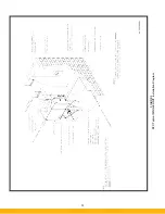
The proper location of your dust collection equipment is very
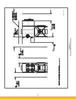
important. Refer to Figures 2 and 3 for typical installation details.
Certain items should be considered when locating the unit, such
as emptying of the dust storage drum(s), filter removal require-
ments, compressed air connections, access to the clean air
plenum, electrical connections, blower location and discharge
direction. The shortest duct length with a minimum number of
elbows will maximize the performance of the unit. Ease of main-
tenance should also be considered when selecting the location
and orientation of the system. Refer to Figure 3 for recommended
clearances.
EXPLOSION HAZARD
In the case of spark producing processes, system
design should incorporate measures to prevent live
sparks from entering the dust collector. Consult local
authorities for the location of the unit and any additional
precautions to consider when collecting combustible,
explosive or hazardous dusts. General warnings and
cautions are provided on page iii and in Section 1.
!
D A N G E R
!
D A N G E R
!
D A N G E R
!
D A N G E R
Содержание SFC
Страница 1: ...Downward Flow Cartridge Dust Collector Owner s Manual Model SFC...
Страница 7: ...v Page intentionally left blank...
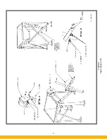
Страница 11: ...4 FIGURE 2 SFC Typical SINGLE UNIT Installation Diagram PARKER PARKER 44 10335 0001...
Страница 12: ...5 FIGURE 3 Recommended Unit Clearances 44 10337 0001...
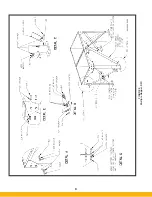
Страница 14: ...7 FIGURE 4 Single Hopper SFC 44 10309 0001...
Страница 15: ...8 FIGURE 5 Multiple Hopper SFC 44 10309 0002...
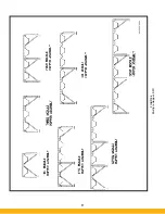
Страница 16: ...9 FIGURE 6 Multiple Hopper SFC 44 10309 0003...
Страница 17: ...10 FIGURE 7 Multiple Modules SFC 44 10310 0001...
Страница 19: ...12 FIGURE 8 SFC Pressure Gauge Installation 44 10333 0001 Rev A...
Страница 20: ...13 FIGURE 9 Solenoid Wiring to Pulse Controls for 2 3 4 and 5 Tier Units...
Страница 21: ...14 FIGURE 10 Pneumatic Valve Assembly 44 10332 0001...
Страница 24: ...17 FIGURE 12 Abrasive Inlet Installation 44 10338 0001...
Страница 27: ...20 FIGURE 16 EDAP Interconnection FIGURE 15 EDAP Installation 48 10007...
Страница 30: ...23 FIGURE 17 SFC Series Door Filter Installation 44 10329 0001...
Страница 37: ...30 7 Illustrated Parts FIGURE 21 SFC Series 44 10330 0001 FIGURE 22 SFC Series Explosion Vents...
Страница 39: ...32 Page intentionally left blank...


