


HY28-2668-01/GC/NA,EU
GOLD CUP
®
Series - Application Manual
Piston Pumps & Motors
1.2
Parker Hannifin Corporation
Hydraulic Pump Division
Marysville, Ohio USA
Section 1
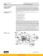
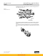
The input shaft passes through the rocker cam and cradle assembly and is splined to the
cylinder barrel. It is available in the following standard configurations:
SAE spline shaft
SAE key shaft
The shaft normally accepts only torsional loads and is not rated for axial and radial loads
imparted by external drive configurations. The displacement of the main system pump is
varied by the rocker cam which rotates in the rocker cradle. Both cam and cradle are loaded in
compression and are very rigid. They do not deflect as do bearing supported trunnions. This
reduction in deflection reduces transmitted noise and increases efficiency. To reduce friction
and the required higher servo pressure, the rocker cam is partially floated by system pressure
exposed to a small area of the cradle surface.
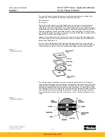
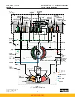
Integrally cast on either side of the rocker cam are a pair of posts to hold the stroking vanes.
The vanes are held in slots in the posts and each consists of a Teflon seal held between two
backup plates. (See figure 1.2)
The seal is held outward against the walls of the stroking chamber by an o-ring and servo
pressure which is fed into the center of the Teflon seal through slots in the backup plates and
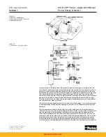
a small shuttle valve. Figure 1.3 shows an assembled stroking vane in the vane chamber.
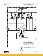
The stroking vanes and chambers are used on all pumps, one on either side. This duality
increases the effective vane area and balances the rocker cam from side to side. It also allows
the pump to be assembled with the control input on either side. Two arcuate shaped stroking
chambers are bolted to either side of the rocker cradle (see figure 1.4). The centerline of the
vane chamber arcuates is the same as the rocker cam center of rotation. The upper and lower
vane chambers on one side (separated by the vane) are connected to the upper and lower
vane chambers on the other side of the rocker cam by a pair of channels through the rocker
cradle.
Figure 1.2
Stroking vane assembly
Figure 1.3
Stroking vane installation
www.comoso.com


