


HY28-2668-01/GC/NA,EU
GOLD CUP
®
Series - Application Manual
Piston Pumps & Motors
3.6
Parker Hannifin Corporation
Hydraulic Pump Division
Marysville, Ohio USA
Section 3
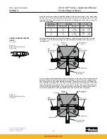
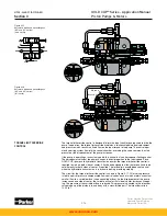
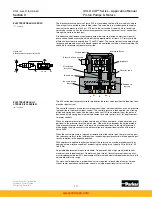
This cylinder control (see Figure 3.7) is available for one side of center pumps. It consists of
two equal length spools in the bore in the input control cover. This control is set to operate on
one side of center only and is spring centered.
Applying 300 psi, 20.6 bar minimum pressure to port X puts pressure through the channel in
the piston on that side. The force generated pushes the rotary servo pin against the spring
loaded piston, causing the rotary servo to move to maximum stroke. When pressure is re-
leased and/or pressure is applied to port Y, the spring and/or pressure on the opposite spool
causes the rotary servo to return to zero stroke.
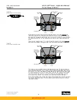
Adjustable stops are used to set the zero stroke position and the maximum stroke position.
This control is intended to be a two position control with the two positions set by the maximum
and minimum displacement stops. If proportinal pressure modulation of servo position is
required, use the 800 control.
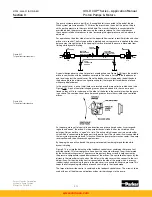
The three position cylinder control (see Figure 3.8) contains two bores. One bore contains two
spring centering spools and springs. A centering pin engages these spools and attaches to
the rotary servo arm through a slot in the cover. The center position adjustment intersects this
bore, providing positive centering adjustment.
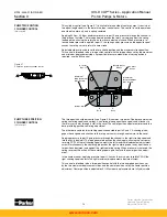
The other bore contains two stroking spools connected to ports X and Y. A stroking pin en-
gages these spools and attaches to the rotary servo arm through another slot in the cover.
Applying pressure to port X puts pressure through the channel in the right stroking spool and
into the cavity behind it. The force generated pushes the stroking pin, causing the servo arm
to rotate CCW, till the left stroking spool contacts the left maximum displacement adjustment
screw. Simultaneously, the centering pin pushes the right centering spool away from the cen-
ter position adjustment and against the right centering spring. When pressure is removed, the
spring reverses this action till the centering spool again contacts the center position adjust-
ment.
In the same manner, applying pressure to port Y causes the servo arm to rotate CW till the
right stroking spool contacts the right maximum displacement adjustment screw.
This control is intended to be a three-position control with the two energized positions set
by the two maximum displacement stops, and the center position set by the center position
adjustment. Center position is adjustable ±5%. Maximum displacements are fully adjustable.
Figure 3.7
Pump two position cylinder control
PUMP TWO POSITION
CYLINDER CONTROL
(2A* control)
PUMP THREE POSITION
CYLINDER CONTROL
(2H* control)
Y
X
C o n t r o l
S p o o l
M
i
n
i
m u m
D
i s
p l a c e m e n t
A d j . S c r e w
R o t a r y S e r v o
S h a f t
C o n t r o l
C o v e r
D o w e l P
i
n
M a x
i
m u m
D
i s
p l a c e m e n t
A d j . S c r e w
X
P o r t
Y
P o r t
www.comoso.com


