


HY28-2668-01/GC/NA,EU
GOLD CUP
®
Series - Application Manual
Piston Pumps & Motors
2.3
Parker Hannifin Corporation
Hydraulic Pump Division
Marysville, Ohio USA
Section 2
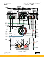
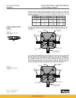
During compensation the flow leaving the opposite vane chamber exits through the opposite
override tube and goes across the dual level relief valve on the low pressure side of the pump.
This valve is set to a lower pressure than the opposite valve, due to the orifices on either
side of the top area. Oil, initially at servo pressure, flows through the equal size orifices which
drop the pressure on top of the poppet to half servo pressure before it exits through the small
check valve into the low pressure work port. Since the annular area is equal to half the area
on top of the dual level relief valve, and the pressure on top of the dual level relief valve is half
servo pressure, the pressure setting of the annular area of the dual level relief valve is equal
to servo pressure plus the spring force. This creates a maximum pressure difference across
the vane actuators, during pressure compensating, approximately equal to servo pressure.
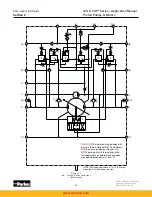
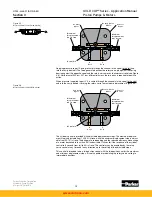
Override pressure must be higher than servo pressure in order to move the rocker cam.
The pilot section of the pressure compensator override circuit consists of a spring loaded
cone and seat and two isolation check valves. The isolation check valves prevent the low pres-
sure side of the circuit from affecting the high pressure setting and also allow individual vents
or remote controls to be connected to either side of the pressure compensator override. There
is also a common vent connection which can control both sides of the override. The pressure
compensator override pilot control is externally adjustable. Please consult installation drawing
for its location on the pumps.
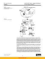
Pressure compensator override pilot pressure is exposed to the top of the pin which pushes
on the pressure modulated servo valve. This makes the servo pressure setting dependent
upon the pressure in the high pressure work port. Since lower control forces are required for
low system pressures, it is possible to reduce the servo pressure without loss of control. This
also reduces parasitic horsepower losses from the servo and replenishing pump. Servo pres-
sure increases approximately 40 psi for every 1000 psi, 4 bar for 100 bar of system pressure.
(For the 30 series, servo pressure increases 62 psi, 4,14 bar per 1000 psi, 69 bar.)
When system pressure drops below the pressure compensator override setting, the manual
rotary servo control, which is still displaced to the original setting, takes over control of the
pump and the pump strokes back to its original setting at a rate controlled by the orifices in
the servo stem.
www.comoso.com


