


HY28-2668-01/GC/NA,EU
GOLD CUP
®
Series - Application Manual
Piston Pumps & Motors
3.10
Parker Hannifin Corporation
Hydraulic Pump Division
Marysville, Ohio USA
Section 3
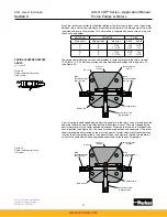
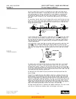
The bypass consists of two tees with integral check valves connected to the high pressure
work ports (see Figure 3.12).
When the bypass is opened, any pressure buildup in the high pressure work ports will open
one of the small check valves and allow flow into the bypass port. This port is open to the
replenishing gallery and the oil flows through the gallery and into the opposite work port at
replenishing pressure.
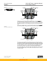
(400 and 500 series)
When both the input rotary servo control and the rocker cam are coincident in the neutral
position, the ball in the control cover (see Figure 3.12) is held off its seat by the adjustable
pin and a hole in the brake and bypass shoe is open to case pressure. This vents the pres-
sure from two cavities which are connected through small orifices to servo pressure. These
cavities are connected to areas on top of both pistons and the pistons move to the left in the
bore. This opens the brake port to case pressure and permits the long pin to shift, opening the
bypass valve.
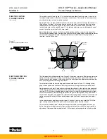
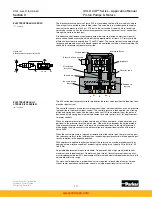
When both the rotary servo input control and the rocker cam are on stroke (see Figure 3.13),
the ball is no longer held off the seat by the adjustable pin (the pin is either moved away from
the ball and seat, or the ball and seat are moved away from the pin) and the hole through the
brake and bypass shoe is plugged off by the servo plate. This stops the flow through the two
orifices and allows pressure to build to servo pressure in the areas to the left of both pistons.
This forces the pistons to the right in their bore, opening the brake port to servo pressure and
closing off the bypass valve with the long pin.
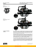
When the input rotary servo is in the neutral position, but the rocker cam is still on stroke (for
example during dynamic braking), the ball is held off the seat, venting the area to the left of
the piston-1; however, the hole in the brake and bypass shoe is still plugged by the servo
plate, keeping servo pressure on piston-2. Piston-2 remains in position, keeping the long pin
blocking the bypass port and the brake port open to servo pressure. This is shown in Figure
3.14.
When the input rotary servo is on stroke and the rocker cam is at zero stroke (for example,
when the rotary servo is initially stroked off of neutral or the transmission is changing direction
of rotation) the ball seats, blocking flow and allows servo pressure to build on piston-1. This
pressure and the light spring force both pistons to the right, keeping the brake port open to
servo pressure and the bypass port closed.
The brake and neutral bypass control has spring centering with a neutral adjustment. The
neutral adjustment can be adjusted for ±5% pump stroke. Adjustable maximum volume
displacement stops are available as an option and can be set anywhere from zero to 100%
stroke. By disassembling the control and adjusting the position of the adjustable pin, the
neutral deadband can be varied. If the pin is shortened (less motion to seat the ball) the
deadband will be reduced.
Figure 3.13
Automatic brake and neutral bypass
400 and 500 series
(input and output on stroke)
S23-12324
M a x . D
i s
p l .
A d j . S c r e w
R o t a r y S e r v o S h a f t
C o n t r o l
C o v e r
M a x . D
i s
p l .
A d j . S c r e w
N e u t r a l Tr
i
m .
A d j . S c r e w
P
i
n
L o n g P
i
n
To R e p l e n
i s
h m e n t
C u
s
t o m e r
S u p p l
i
e d
B r a k e
S e r v o
P l a t e
B y p a
s s
S h o e
B a l l
A d j u
s
t a b l e
P
i
n
S y
s
.
P r e
s s
.
P
i s
t o n - 1
P
i s
t o n - 2
L
i
g h t S p r
i
n g
H e a v y S p r
i
n g
P o r t Z
www.comoso.com


