


HY28-2668-01/GC/NA,EU
GOLD CUP
®
Series - Application Manual
Piston Pumps & Motors
2.13
Parker Hannifin Corporation
Hydraulic Pump Division
Marysville, Ohio USA
Section 2
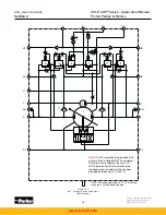
The circuitry provided in the GOLD CUP
®
hydrostatic pumps provides some special features
not found in other transmissions pumps.
1. The servo pressure in the GOLD CUP
®
line varies with system pressure without reducing
control ability. This gives a higher efficiency with a corresponding reduced heat load
to the circuit.
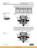
2. There is no need for cross port relief valves external to the pump. The relief sequence valve
circuit in the pressure compensator override circuit accomplishes this function. Should the
pump not be able to continue to change its stroke for any reason, flow from the high pres-
sure work port will go across the high pressure sequence valve, across the dual level relief
valve and into the replenishing gallery where it is carried to the opposite work port.
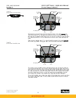
3. All excess flows from the control valves, with the exception of the rotary servo, are directed
into the replenishing gallery. This prevents momentary loss of replenishing pressure when
the pump is responding to controls.
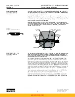
4. It is possible to prevent momentary cavitation in the pump, at low shaft speed and high
pressure, by connecting case drains from the motor and pump together and passing them
through a 40 psi (2.8 bar) check valve before plumbing to the reservoir. This insures that
should there not be sufficient replenishing flow, the case drain leakages are available for
replenishing. This is due to the replenishing relief valve’s capability of accepting flow from
the case drain into the replenishing gallery, if there is sufficient pressure in the case.
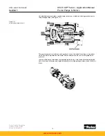
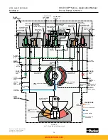
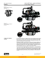
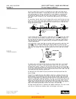
Package motors contain the shuttle valve and the low pressure replenishing relief valve. The
circuitry contained in the motor is shown in Figure 2.5. The shuttle spool is shifted to one
side by system pressure. When shifted the low pressure side of the loop is connected to the
primary side of the low pressure replenishing relief valve. The low pressure replenishing relief
valve is set to a lower pressure than the replenishing relief valve in the pump. This insures
that all the available replenishing flow enters the circuit for cooling. Optional orifices may be
installed in the shuttle-relief block to limit the flow through the shuttle. With the orifices, flow
through the shuttle is limited and the shift is very positive.
PACKAGE MOTOR CIRCUITRY
Figure 2.5
GOLD CUP
®
package motor circuit
www.comoso.com


