


HY28-2668-01/GC/NA,EU
GOLD CUP
®
Series - Application Manual
Piston Pumps & Motors
3.4
Parker Hannifin Corporation
Hydraulic Pump Division
Marysville, Ohio USA
Section 3
Adjustable stops are available as an option on the spring centered rotary servo with and with-
out automatic brake and bypass valve. Adjustable stops are standard on all other controls.
The relationship between number of turns (T) of the adjusting screws and pump or motor
stroke is:
Manual screw adjustment........................ 6.72 turns full to zero
Motor cylinder control .............................. 4.7 turns full to 30% stroke
Three position cylinder control ................ 6.72 turns full to zero
Spring centered rotary servo................... 6.72 turns full to zero
Hydraulic stroker (800 series) ................. 5.04 turns full to zero
(for motors) .............................................. 3.5 turns full to 30% stroke
Electrohydraulic stroker (500 series)....... 8.5 turns full to zero
(for motors) .............................................. 6 turns full to 30% stroke
Electrohydraulic stroker (900 series)....... 5.04 turns full to zero
(for motors) .............................................. 3.5 turns full to 30% stroke
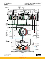
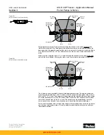
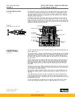
The manual screw adjustment control is available as an option to allow the pump displace-
ment to be set and left at that setting. It can also serve as the maximum volume adjustment
when the pump is used as a pressure compensator pump. In this control, the dowel pin in the
rotary servo arm is pushed to maximum displacement by the spring pushing on the spool (see
Figure 3.4).
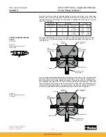
The maximum displacement screw limits the maximum volume to which the rotary servo is
pushed and is adjustable from full to zero displacement. An adjustable minimum stop is lo-
cated on the opposite side of the control cover and is adjustable from zero to 50% of max. full
stroke. During operation the rotary servo may be manually destroked off of the manual screw
stop by a torque of 20 lbs-in., 2.3 Nm on the rotary servo input shaft.
The relationship between the number of turns of the manual screw and stroke is the same as
given in the adjustable stop description above.
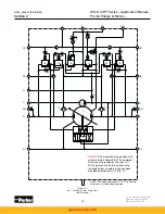
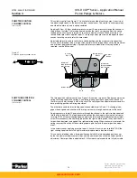
The motor cylinder control consists of two spools in the bore in the input control cover, one
longer than the other. This limits stroke to one side of center, 30% stroke to full stroke. (see
Figure 3.5) This control is spring offset to maximum displacement.
ADJUSTABLE STOPS
Control Option A
Figure 3.4
Manual screw adjustment
MANUAL SCREW ADJUSTMENT
(1** control)
MOTOR CYLINDER CONTROL
(2A* control)
S p o o l
M
i
n
i
m u m
D
i s
p l .
A d j . S c r e w
R o t a r y S e r v o
S h a f t
C o n t r o l
C o v e r
D o w e l P
i
n
M a x .
D
i s
p l a c e m e n t
A d j . S c r e w
www.comoso.com


