HY28-2668-01/GC/NA,EU
GOLD CUP
®
Series - Application Manual
Piston Pumps & Motors
iv
Parker Hannifin Corporation
Hydraulic Pump Division
Marysville, Ohio USA
Contents
Electrohydraulic stroker (500 series) ....................................................................................3.14
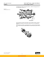
Figure 3.20 Electrohydrauic stroker (zero stroke) .............................................................3.14
Figure 3.21 Electrohydraulic stroker (on stroke) ...............................................................3.15
Figure 3.22 Stroke vs. current ..........................................................................................3.15
Hydraulic stroker (800 series) ...............................................................................................3.15
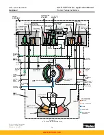
Figure 3.23 Hydraulic stroker (centered) ..........................................................................3.16
Figure 3.24 Hydraulic stroker (on stroke) .........................................................................3.16
Electrohydraulic servo (HI IQ ) (700 series) .........................................................................3.17
Figure 3.25 Electrohydraulic servovalve (HI-IQ) ...............................................................3.17
Electrohydraulic stroker (900 series) ....................................................................................3.17
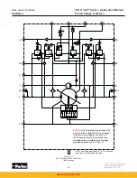
Figure 3.26 900 series hydraulic circuit ............................................................................3.18
Introduction .............................................................................................................................4.1
Remote control of pressure compensator override ................................................................4.1
Figure 4.1 Circuit to control speed of venting compensator ...............................................4.1
Figure 4.2 Remote control of multiple PCOR .....................................................................4.1
Figure 4.3 Remote control of PCOR by pressure sources .................................................4.2
Load sensing ..........................................................................................................................4.2
Figure 4.4 Load sensing .....................................................................................................4.2
Constant speed drives ............................................................................................................4.3
Figure 4.5 Constant speed drive ........................................................................................4.3
Dead man control ...................................................................................................................4.3
Overhauling load-dynamic braking .........................................................................................4.3
Replenishment requirements ..................................................................................................4.4
Figure 4.6 Case pressure replenishment circuit .................................................................4.4
Figure 4.7 Additional replenishment flow ............................................................................4.5
Engine startup ........................................................................................................................4.5
Cold startup ............................................................................................................................4.5
New system or new component startup .................................................................................4.6
System filtration ......................................................................................................................4.6
Cleaning procedures ..............................................................................................................4.7
Shaft type selection ................................................................................................................4.7
Applying splined shafts ...........................................................................................................4.8
Applying keyed shafts .............................................................................................................4.8
Series6 Variable volume pump with 1.07 in
3
/rev., 17,5 cc/rev. aux. pump...............................5.1
Series6 Variable volume motor ...............................................................................................5.2
Series7 Variable volume pump with 1.07 in
3
/rev., 17,5 cc/rev. aux. pump...............................5.3
Series7 Variable volume motor ...............................................................................................5.4
Series8 Variable volume pump with 1.07 in
3
/rev., 17,5 cc/rev. aux. pump...............................5.5
Series11 Variable volume pump with 2x1.07 in
3
/rev., 2x17,5 cc/rev. aux. pump .....................5.6
Series11 Variable volume motor .............................................................................................5.7
Series14 Variable volume pump with 2x1.07 in
3
/rev., 2x17,5 cc/rev. aux. pump .....................5.8
Series14 Variable volume motor .............................................................................................5.9
Series24 Variable volume pump with 2.81 in
3
/rev., 46 cc/rev. aux. pump..............................5.10
Series24 Variable volume motor ...........................................................................................5.11
Series30 Variable volume pump with 2.81 in
3
/rev., 46 cc/rev. aux. pump..............................5.12
Fluid power formulas ..............................................................................................................6.1
Pg1 Pump ordering code ........................................................................................................6.2
Pg2 Pump ordering code ........................................................................................................6.3
Pg1 Motor ordering code ........................................................................................................6.4
Pg2 Motor ordering code ........................................................................................................6.5
Pump control combinations ....................................................................................................6.6
Motor control combinations ....................................................................................................6.7
Notes ......................................................................................................................................7.1
Offer of Sale ...........................................................................................................................7.2
SECTION 3
GOLD CUP
®
controls (continued)
SECTION 4
GOLD CUP
®
application suggestions
SECTION 5
GOLD CUP
®
performance curves
SECTION 6
Reference information
SECTION 7
Offer of Sale
www.comoso.com


