Chapter 3 Electrical Installation - 47 -
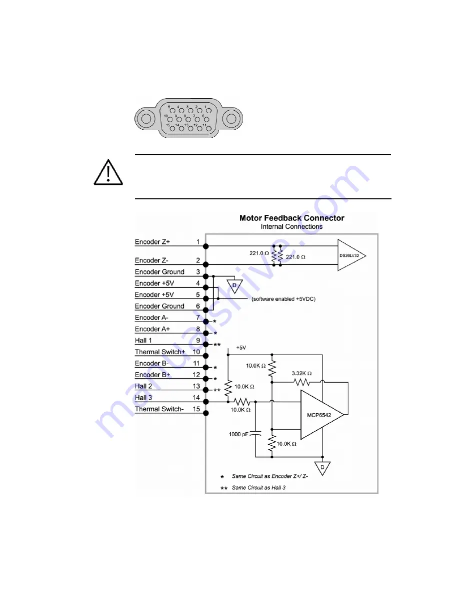
Motor Feedback Connector
Inputs for the resolver feedback, motor thermal switch, and hall effects are
located on the 15-pin Motor Feedback connector.
Figure 29
MOTOR FEEDBACK
connector, female drive connector pinout
Important —
Encoder inputs use a DS26LV32 differential line receiver.
Parker Hannifin recommends 26LS31 (or compatible) differential line driven
encoders.
Single ended encoders are
not
compatible.
Figure 30
MOTOR FEEDBACK
connector, internal circuit diagram
Artisan Technology Group - Quality Instrumentation ... Guaranteed | (888) 88-SOURCE | www.artisantg.com


