


English
5/8
ICE150-230
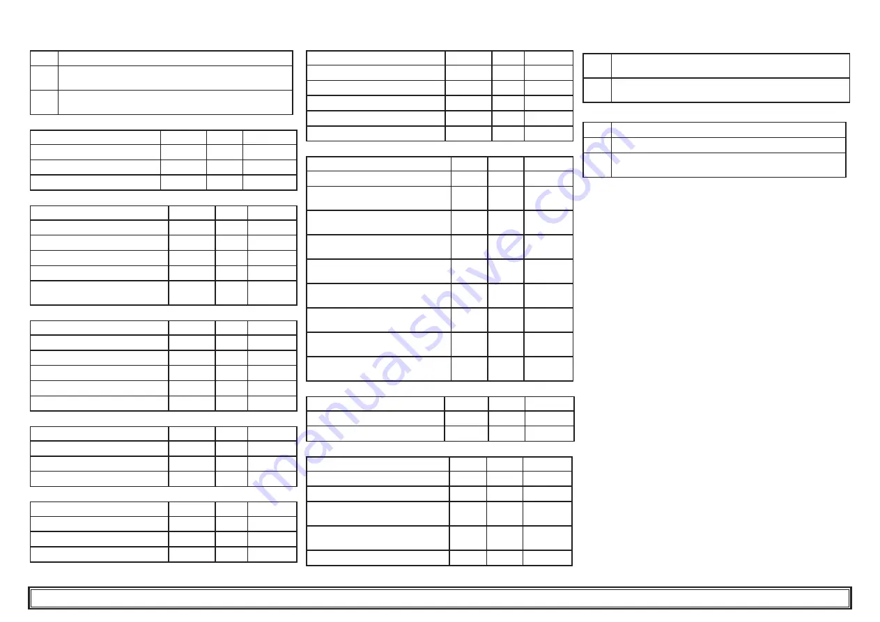
4.4.1.2
Alarm relay management
0
Relay normally deactivated, excited by an alarm.
1
Relay normally excited (also with control OFF), deactivated
by an alarm.
2
Relay normally excited (only with control ON), deactivated
by an alarm or with control OFF.
4.4.2 Temperature
control
PARAMETER
CODE
TYPE
DEFAULT
Temperature control set point
SEt
D
--
Temperature control differential
dIF
D
4.0
Set point lower limit
LI5
U
5.0
4.4.3
B1 sensor parameters
PARAMETER
CODE
TYPE
DEFAULT
High temperature confi guration
cHAI
U
0
High temperature alarm
HAI
D
60.0
Low temperature alarm
LAI
D
-20.0
Sensor calibration
CAI
U
0.0
Low temperature alarm reset
differential
dbI
U
1.0
4.4.4
B2 sensor parameters
PARAMETER
CODE
TYPE
DEFAULT
High temperature confi guration
cHA2
U
0
High temperature alarm
HA2
U
60.0
Low temperature alarm
LA2
U
3.0
Sensor calibration
CA2
U
0.0
B2 sensor presence
Ab2
U
1.0
4.4.5
B3 sensors parameters
PARAMETER
CODE
TYPE
DEFAULT
High temperature alarm
HA3
U
60.0
Low temperature alarm
LA3
U
-20.0
Sensor calibration
CA3
U
0.0
4.4.6
B5 sensors parameters
PARAMETER
CODE
TYPE
DEFAULT
High temperature alarm
HA5
U
60.0
Low temperature alarm
LA5
U
-20.0
Sensor calibration
CA5
U
0.0
4.4.7
B7 sensor parameters
PARAMETER
CODE
TYPE
DEFAULT
High temperature confi guration
cHA7
U
0
High temperature alarm
HA7
U
60.0
Low temperature alarm
LA7
U
3.0
Sensor calibration
CA7
U
0.0
B7 sensor presence
Ab7
U
1.0
4.4.8 Compressor
parameters
PARAMETER
CODE
TYPE
DEFAULT
Compressor rotation
rot
U
2
Compressor 1 operation hour
counter
HI
D
-
Compressor 3 operation hour
counter
H3
D
-
Compressor 2 operation hour
counter
H2
D
-
Compressor 4 operation hour
counter
H4
D
-
Compressor 1 hour counter
threshold
tHI
U
0
Compressor 3 hour counter
threshold
tH3
U
0
Compressor 2 hour counter
threshold
tH2
U
0
Compressor 4 hour counter
threshold
tH4
U
0
4.4.9 Pump
parameters
PARAMETER
CODE
TYPE
DEFAULT
Pump stop delay
dP5
U
5
Pump start delay
dPA
U
5
4.4.10
Antifreeze heater parameters
PARAMETER
CODE
TYPE
DEFAULT
Set point adjustment (B1)
SEA
U
7.0
Temperature control differential (B1)
dIA
U
1.0
Antifreeze heater operating mode
(see para. 4.4.8.1)
FUA
U
0
Antifreeze heater activation mode
(see para. 4.4.8.2)
AbrA
U
2
Activation set point (B3)
ArA
U
5.0
4.4.10.1 FUA antifreeze heater operating mode
0
Temperature control by B1, activation by B3 (ambient
temperature sensor)
1
Temperature control by B3 (ambient temp. sensor) with
ARA set point.
4.4.10.2 AbrA antifreeze heater activation mode
0
Activation only when controller is ‘On’
1
Activation also when controller is ‘Off’
2
Activation also when controller is ‘Off’. During heater opera-
tion the pump is activated.
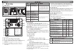
4.5 Parameter management
4.5.1
Temperature setting (see fi g.1)
1. 1. Turn the main swicth (QS) to “ON” and wait for the temperature
visualization.
2. Press buttons “
P3
” and “
P5
” together, to enter into “
dIrE
” (D)
parameters.
3. Press button “
P4
” to select “
SEt
” parameter, press the button
“
P5
” to confi rm.
4. Change the value, using the up and down arrow buttons “
P3
” and
“
P4
”, then press button “
P5
” to confi rm.
6. Press the button “
P3
” to return on “
dIrE
”
parameter.
7. Press the button “
P5
” to exit.
4.5.2
Differential setting (see fi g.1)
1. Turn the main swicth (QS) to “ON” and wait for the temperature
visualization.
2. Press buttons “
P3
” e “
P5
” together, to enter into “
dIrE
” (D)
parameters.
3. Press button two times “
P4
” to select “
diF
” parameter, press the
button “
P5
” to confi rm.
4. Change the value, using the up and down arrow buttons “
P3
” and
“
P4
”, then press button “
P5
” to confi rm.
6. Press the button two times “
P3
” to return on “
dIrE
”
parameter.
7. Press the button “
P5
” to exit.
4.5.3
Visualization sensors B1,B2...
“B1” is the “set” sensor of the macchine.
1. Start the chiller.
2. Press the button “
P4
” to visualize the temperature of the next sen-
sor.
3. Press the button “
P5
” to visualize the sensors “
b01
” ..“
b02
”....
It is recommended to leave on the display the B1 “set” sensor.


