


Table 11. Fault Diagnosis
Symptom
Check
No front panel indicators lit.
Check input supplies.
Check ac supply input fuse (located in rear panel ac
connector) and dc supply fuse.
Check output of switched mode power supply (SMPS). This
should be +15.6 V dc (wrt 0 V) at TP21 (located next to CN10)
of the Interface PCB (see Figures 7 and 11). If the SMPS is
suspect, remove it from the base station and test it on the
workbench ensuring a load is connected across its output.
Fault, or error code displayed at front panel.
Fault and error codes are displayed on the front panel to
indicate faults detected by the radio module. These codes are
detailed in Table 12.
Transmit function not operating correctly.
Transmit inhibit indicator flashing.
External transmit inhibit facility is deliberately or inadvertently
enabled. This facility is enabled when pin 14 on the base
station's Facilities connector is grounded (see Table 6 on
page 34.
Transmit function not operating correctly. No
fault code displayed.
Complete the ‘Transmit Power and Frequency Accuracy Test’
detailed on page 50. If the test fails, check for any obvious
problems such as a faulty PTT switch. Note also that the
signal from the microphone connector passes through the
Interface module before being connected to the radio module
(see Figures 6 and 7). If the signals are correct at the radio
input, then change the radio module.
Receive function not operating correctly. No
fault code displayed.
If some signals are not being received, refer to the operating
instructions and check the squelch level is correctly set.
Complete the ‘Receiver Sensitivity Check’ on page 52. If the
test fails, use Figures 6 and 7 to determine where the fault lies.
For example, audio out of the radio module can be monitored
at the Interface module connector CN8 pins 3 and 7. The
Interface module's audio output to the loudspeaker can then
be monitored on CN7 pins 13 and 14. Using Figures 6 and 7
should enable the fault to be diagnosed to either the radio
module, or the Interface PCB.
If the ‘Receiver Sensitivity Check’ is OK, the fault is probably
in the antenna system.
T6M Base Station User Guide
Page 54
Содержание T6M
Страница 1: ...T6M Base Station User Guide Handbook Part Number 31 360T6MBS...
Страница 12: ...Intentionally Blank T6M Base Station User Guide Page 12...
Страница 16: ...Intentionally Blank T6M Base Station User Guide Page 16...
Страница 48: ...Intentionally Blank T6M Base Station User Guide Page 48...
Страница 56: ...Intentionally Blank T6M Base Station User Guide Page 56...
Страница 58: ...Intentionally Blank T6M Base Station User Guide Page 58...
Страница 59: ...BT6MBS 01 Front and Rear Layout Figure 1...
Страница 60: ...BT6MBS 13 Rack Mounted Version Figure 2...
Страница 61: ...GA10642 Iss 1 Key to Front Panel Controls Figure 3 For description of controls see text in chapter 3...
Страница 62: ...BT6MBS 11 External Connection Diagram Figure 4...
Страница 63: ...BT6MBS 10 Enclosure Securing Detail Figure 5...
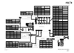
Страница 64: ...Base Station Block Diagram Figure 6 GA10547 Iss 3...
Страница 65: ...Base Station Interconnection Diagram Figure 7 GA10548 Iss 3...
Страница 66: ...Base Station Layout Diagram Figure 8 GA10719 Iss 1...
Страница 69: ...Interface PCB Layout Diagram Figure 11 GA10751 Iss 1...
Страница 70: ...BT6MBS 12 1 Cable Termination at the N Type Connector Figure 12...