


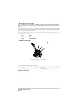


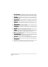


CONNECTING AN AC INPUT SUPPLY
An ac input supply must be connected to the base station using the supply connector provided (Table 3,
item 3). The free end of the cable should be terminated with a connector suitable for the local mains
supply.
The T6M base station is a class 1 equipment. The ac supply cable must have a green-and-yellow
protective earthing conductor electrically connected to the protective earthing terminal of the equipment
connector, and the supply output connector.
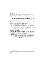
The ac supply cable should be colour coded in accordance with the electrical appliance (colour code)
regulations for the UK. That is:
Line:
Brown
Neutral:
Blue
Earth:
Green-and-yellow
Connections are shown below.
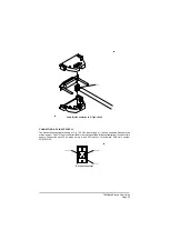
CONNECTING A PC TO THE BASE STATION
To modify the base station's personality, the microphone is disconnected from the
Microphone/Diagnostics connector and is replaced by an RS232 cable connected to a laptop, or PC. The
cable is part of the T6M programming kit, part number 70-T6MPMKIT. Figure 4 shows the connections
used for the RS232 cable.
T6M Base Station User Guide
Page 36
Base Station's Chassis AC Connector
Содержание T6M
Страница 1: ...T6M Base Station User Guide Handbook Part Number 31 360T6MBS...
Страница 12: ...Intentionally Blank T6M Base Station User Guide Page 12...
Страница 16: ...Intentionally Blank T6M Base Station User Guide Page 16...
Страница 48: ...Intentionally Blank T6M Base Station User Guide Page 48...
Страница 56: ...Intentionally Blank T6M Base Station User Guide Page 56...
Страница 58: ...Intentionally Blank T6M Base Station User Guide Page 58...
Страница 59: ...BT6MBS 01 Front and Rear Layout Figure 1...
Страница 60: ...BT6MBS 13 Rack Mounted Version Figure 2...
Страница 61: ...GA10642 Iss 1 Key to Front Panel Controls Figure 3 For description of controls see text in chapter 3...
Страница 62: ...BT6MBS 11 External Connection Diagram Figure 4...
Страница 63: ...BT6MBS 10 Enclosure Securing Detail Figure 5...
Страница 64: ...Base Station Block Diagram Figure 6 GA10547 Iss 3...
Страница 65: ...Base Station Interconnection Diagram Figure 7 GA10548 Iss 3...
Страница 66: ...Base Station Layout Diagram Figure 8 GA10719 Iss 1...
Страница 69: ...Interface PCB Layout Diagram Figure 11 GA10751 Iss 1...
Страница 70: ...BT6MBS 12 1 Cable Termination at the N Type Connector Figure 12...