


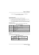

Table 6. Base station Facilities Connector Pin-Out
Base Station's
Facilities
Connector Pin
Number
Signal
Input or
Output
Description
1
Ground
-
0 V.
2
3
Tape +
Tape -
Output
A balanced 600
W
twisted pair providing audio to drive
a tape recording system. The output level is 0 dBm
(sine wave on 600
W
) for 85% modulation depth.
4
Audio operated
squelch
Output
0 V when received audio having a modulation depth
>20% is present. Open circuit at other times. This
signal can be used as an external ‘busy’ indication.
5
6
7
8
9
10
Control Desk Rx +
Control Desk Rx -
Control Desk Tx +
Control Desk Tx -
Control Desk PTT +
Control Desk PTT -
Output
Input
Input
A 6-wire system comprising two 600
W
twisted pair
balanced lines for Rx and Tx audio, plus a line pair for
PTT.
The audio line levels are 0 dBm (sine wave on 600
W
)
for 85% modulation depth. PTT can be activated either
by shorting together the PTT lines, or by phantom
keying on the Tx lines. Note that Control Desk PTT - is
internally connected to 0 V.
11
12
13
Not connected
Not connected
Not connected
-
-
14
External Tx inhibit
Input
When this line is connected to 0 V, the base station
cannot be keyed.
15
Ground
-
0 V.
T6M Base Station User Guide
Page 34
Содержание T6M
Страница 1: ...T6M Base Station User Guide Handbook Part Number 31 360T6MBS...
Страница 12: ...Intentionally Blank T6M Base Station User Guide Page 12...
Страница 16: ...Intentionally Blank T6M Base Station User Guide Page 16...
Страница 48: ...Intentionally Blank T6M Base Station User Guide Page 48...
Страница 56: ...Intentionally Blank T6M Base Station User Guide Page 56...
Страница 58: ...Intentionally Blank T6M Base Station User Guide Page 58...
Страница 59: ...BT6MBS 01 Front and Rear Layout Figure 1...
Страница 60: ...BT6MBS 13 Rack Mounted Version Figure 2...
Страница 61: ...GA10642 Iss 1 Key to Front Panel Controls Figure 3 For description of controls see text in chapter 3...
Страница 62: ...BT6MBS 11 External Connection Diagram Figure 4...
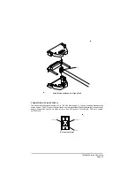
Страница 63: ...BT6MBS 10 Enclosure Securing Detail Figure 5...
Страница 64: ...Base Station Block Diagram Figure 6 GA10547 Iss 3...
Страница 65: ...Base Station Interconnection Diagram Figure 7 GA10548 Iss 3...
Страница 66: ...Base Station Layout Diagram Figure 8 GA10719 Iss 1...
Страница 69: ...Interface PCB Layout Diagram Figure 11 GA10751 Iss 1...
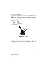
Страница 70: ...BT6MBS 12 1 Cable Termination at the N Type Connector Figure 12...