


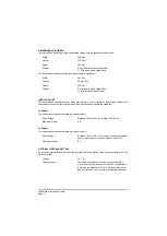


RECEIVE CIRCUIT
The specification of the receive circuit is listed below.
Sensitivity
-104 dBm at 30% modulation depth for 10 dB (S+N):N.
Selectivity
8.33 kHz spaced: <6 dB at ±3 kHz; >60 dB at ±8.33 kHz.
25 kHz spaced: <6 dB at ±8.5 kHz; >70 dB at ±25 kHz.
Intermodulation suppression
>70 dB.
Spurious response suppression
>80 dB.
Audio power output
2 W into 8 ohm integral speaker (<10% THD).
Distortion
<10% THD for 90% modulation depth.
RF input impedance
50 ohms.
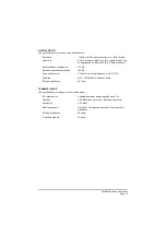
TRANSMIT CIRCUIT
The specification of the transmit circuit is listed below.
RF output power
Adjustable between approximately 5 and 12 W.
Spurious
<-46 dBm when more than 1 MHz from the carrier.
Harmonics
<-36 dBm.
Modulation depth
Up to 85%. Compression above 85% to prevent over
modulation.
RF load impedance
50 ohms.
Frequency stability
±
1.5 ppm.
T6M Base Station User Guide
Page 15
Содержание T6M
Страница 1: ...T6M Base Station User Guide Handbook Part Number 31 360T6MBS...
Страница 12: ...Intentionally Blank T6M Base Station User Guide Page 12...
Страница 16: ...Intentionally Blank T6M Base Station User Guide Page 16...
Страница 48: ...Intentionally Blank T6M Base Station User Guide Page 48...
Страница 56: ...Intentionally Blank T6M Base Station User Guide Page 56...
Страница 58: ...Intentionally Blank T6M Base Station User Guide Page 58...
Страница 59: ...BT6MBS 01 Front and Rear Layout Figure 1...
Страница 60: ...BT6MBS 13 Rack Mounted Version Figure 2...
Страница 61: ...GA10642 Iss 1 Key to Front Panel Controls Figure 3 For description of controls see text in chapter 3...
Страница 62: ...BT6MBS 11 External Connection Diagram Figure 4...
Страница 63: ...BT6MBS 10 Enclosure Securing Detail Figure 5...
Страница 64: ...Base Station Block Diagram Figure 6 GA10547 Iss 3...
Страница 65: ...Base Station Interconnection Diagram Figure 7 GA10548 Iss 3...
Страница 66: ...Base Station Layout Diagram Figure 8 GA10719 Iss 1...
Страница 69: ...Interface PCB Layout Diagram Figure 11 GA10751 Iss 1...
Страница 70: ...BT6MBS 12 1 Cable Termination at the N Type Connector Figure 12...