


(4)
Check that the display shows tESt and after a few seconds it changes to show the current
power level setting (a number between 1 and 240 representing approximately 6 to 12 watts).
(5)
Press the SQL button to select the test frequency 127.500 MHz. The test frequency is
displayed for a couple of seconds and the display then reverts to the power setting.
Note …
Using the SQL key to select a test frequency always selects a 25 kHz spaced channel.
Squelch is automatically switched off in Test mode.
(6)
Key the transmitter and note the wattmeter's reading.
(7)
With the transmitter de-keyed, use the CH
s
and CH
t
buttons to increment or decrement
the power setting in steps of 1. Alternatively, use the SEL
s
and SEL
t
buttons to increment
or decrement the power setting in steps of 10. Then key the transmitter and note the
wattmeter's reading.
The power setting cannot be adjusted when the transmitter is
keyed
. Adjust the power output until the required power is set (nominally 8 watts).
Note …
The transmit indicator lights when the transmitter is keyed. If a fault is detected, the
indicator does not light. No fault codes, however, are displayed in Test mode.
(8)
Key the transmitter and check that the frequency counter reads between 127.499808 and
127.500192 MHz.
(9)
To save the new power setting in the base station's memory, press and keep pressed the
front panel Power button. Without releasing the Power button, press and release the PRI
button, then the SCN button, and finally the SQL button.
(10) When the new setting is saved, the display shows ‘S’ and two short beeps are heard.
Release the Power button.
(11) To switch off without saving the new power setting, press and release the Power button. The
display shows nS and a single long tone is heard.
(12) Enter test mode again by pressing, and keeping pressed, the front panel Power button.
Without releasing the Power button, press and release the SQL button, then the SCN button,
and finally the PRI button. Release the Power button.
(13) Check that the display shows tESt and after a few seconds it changes to show the current
power level setting.
(14) Press the SQL button to select the test frequency 118.000 MHz.
(15) Key the transmitter and check that the wattmeter reads between 6 and 12 watts. Check that
the frequency counter reads between 117.999823 and 118.000177 MHz.
(16) Press the SQL button to select the test frequency 136.975 MHz.
(17) Key the transmitter and check that the wattmeter reads between 6 and 12 watts. Check that
the frequency counter reads between 136.974745 and 136.975205 MHz.
(18) On completion, switch off the base station and disconnect the test equipment. Restore the
base station ready for operational use.
T6M Base Station User Guide
Page 51
Содержание T6M
Страница 1: ...T6M Base Station User Guide Handbook Part Number 31 360T6MBS...
Страница 12: ...Intentionally Blank T6M Base Station User Guide Page 12...
Страница 16: ...Intentionally Blank T6M Base Station User Guide Page 16...
Страница 48: ...Intentionally Blank T6M Base Station User Guide Page 48...
Страница 56: ...Intentionally Blank T6M Base Station User Guide Page 56...
Страница 58: ...Intentionally Blank T6M Base Station User Guide Page 58...
Страница 59: ...BT6MBS 01 Front and Rear Layout Figure 1...
Страница 60: ...BT6MBS 13 Rack Mounted Version Figure 2...
Страница 61: ...GA10642 Iss 1 Key to Front Panel Controls Figure 3 For description of controls see text in chapter 3...
Страница 62: ...BT6MBS 11 External Connection Diagram Figure 4...
Страница 63: ...BT6MBS 10 Enclosure Securing Detail Figure 5...
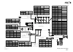
Страница 64: ...Base Station Block Diagram Figure 6 GA10547 Iss 3...
Страница 65: ...Base Station Interconnection Diagram Figure 7 GA10548 Iss 3...
Страница 66: ...Base Station Layout Diagram Figure 8 GA10719 Iss 1...
Страница 69: ...Interface PCB Layout Diagram Figure 11 GA10751 Iss 1...
Страница 70: ...BT6MBS 12 1 Cable Termination at the N Type Connector Figure 12...