


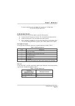


Transmit Power and Frequency Accuracy Test
To check the base station's transmit power, and the accuracy of the carrier frequency, carry out the
following procedure:
(1)
Isolate power from the base station and connect the test equipment as shown below. Ensure
the wattmeter is switched to forward power.
(2)
Reconnect the power and ensure the base station's rear panel Power switch is set to on.
(3)
To enter Test mode switch on the base station by pressing, and keeping pressed, the front
panel Power button. Without releasing the Power button, press and release the SQL button,
then the SCN button, and finally the PRI button. Release the Power button.
T6M Base Station User Guide
Page 50
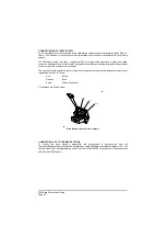
Transmit Power and Frequency Accuracy Test - Test Equipment Connection
Base Station Front Panel Power Button Location
Содержание T6M
Страница 1: ...T6M Base Station User Guide Handbook Part Number 31 360T6MBS...
Страница 12: ...Intentionally Blank T6M Base Station User Guide Page 12...
Страница 16: ...Intentionally Blank T6M Base Station User Guide Page 16...
Страница 48: ...Intentionally Blank T6M Base Station User Guide Page 48...
Страница 56: ...Intentionally Blank T6M Base Station User Guide Page 56...
Страница 58: ...Intentionally Blank T6M Base Station User Guide Page 58...
Страница 59: ...BT6MBS 01 Front and Rear Layout Figure 1...
Страница 60: ...BT6MBS 13 Rack Mounted Version Figure 2...
Страница 61: ...GA10642 Iss 1 Key to Front Panel Controls Figure 3 For description of controls see text in chapter 3...
Страница 62: ...BT6MBS 11 External Connection Diagram Figure 4...
Страница 63: ...BT6MBS 10 Enclosure Securing Detail Figure 5...
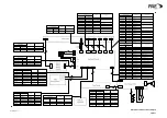
Страница 64: ...Base Station Block Diagram Figure 6 GA10547 Iss 3...
Страница 65: ...Base Station Interconnection Diagram Figure 7 GA10548 Iss 3...
Страница 66: ...Base Station Layout Diagram Figure 8 GA10719 Iss 1...
Страница 69: ...Interface PCB Layout Diagram Figure 11 GA10751 Iss 1...
Страница 70: ...BT6MBS 12 1 Cable Termination at the N Type Connector Figure 12...