Paradyne Hotwire 7976 Скачать руководство пользователя страница 37

Initial Startup and Configuration

 3-13

7976-A2-GB20-10

August 1998

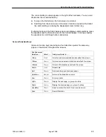
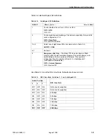
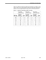
Table 3-4 provides the maximum payload rates achievable for each DSL line rate
and the number of time slots required to achieve that payload rate depending on
whether you are using signaling (time slots 0 and 16) or data only (time slot 0).

Table 3-4.

Fixed Rate Payload Rates and DSL Line Rates

Voice Mode
(G.703 to G.703)

Data Mode
(G.703 to G.703)

Data Mode
(G.703 to EIA-530)

DSL Line
Rate (kbps)

Maximum
Payload
Rate (kbps)

Time
slots

Maximum
Payload
Rate (kbps)

Time
slots

Maximum
Payload
Rate (kbps)

Time
slots

2064

1920

30

1984

31

1984

31

1552

1408

22

1472

23

1536

24

1040

896

14

960

15

1024

16

784

640

10

704

11

768

12

528

384

6

448

7

512

8

400

256

4

320

5

384

6

Содержание Hotwire 7976

Страница 1: ...HOTWIRE MODEL 7976 M SDSL STANDALONE TERMINATION UNIT WITH G 703 INTERFACE USER S GUIDE Document No 7976 A2 GB20 10 August 1998...

Страница 2: ...herein will be documented and issued as a new release to this manual Warranty Sales and Service Information Contact your local sales representative service representative or distributor directly for...

Страница 3: ...ables are provided with this product Special cables which may be required by the regulatory inspection authority for the installation site are the responsibility of the customer 7 When installed in th...

Страница 4: ...mful interference to radio communications Operation of this equipment in a residential area is likely to cause harmful interference in which case the user will be required to correct the interference...

Страница 5: ...Unit Features 1 2 H Network Configuration 1 3 H Front Panel LED Status Indicators 1 4 H Rear Panel Interface Connections 1 4 H SNMP Trap Support 1 5 2 Using the Asynchronous Terminal Interface H User...

Страница 6: ...nternal Switches 3 6 Switchpack Locations 3 7 Switchpack Definitions 3 8 H Accessing and Displaying Configuration Options 3 10 H Configuration Edit Display 3 11 H Configuring AutoRate 3 12 H Configura...

Страница 7: ...Device Tests 5 8 Lamp Test 5 8 H Ending an Active Test 5 9 6 Messages and Troubleshooting H Overview 6 1 H Configuring SNMP Traps 6 2 H Device Messages 6 3 H Troubleshooting 6 5 7 Security H Overview...

Страница 8: ...Sessions Options A 11 H Communication Protocol Options A 13 SNMP Traps Options A 16 B Standards Compliance for SNMP Traps H SNMP Traps B 1 warmStart B 1 authenticationFailure B 1 linkUp and linkDown B...

Страница 9: ...erminal Interface Provides instructions for accessing the user interface and navigating through the screens Chapter 3 Initial Startup and Configuration Provides procedures for setting up the user inte...

Страница 10: ...cations network and port interfaces power consumption values and accessory part numbers Glossary Defines acronyms and terms used in this document Index Lists key terms acronyms concepts and sections i...

Страница 11: ...payload rates over a 2 wire full duplex circuit over varying distances based on the conditions of the 2 wire loop Examples include support for router multiplexer and PBX connections on 24 gauge 5 mm...

Страница 12: ...lity over the M SDSL link and download capabilities H Asynchronous Terminal Interface ATI Provides a menu driven VT100 compatible terminal interface for configuring and managing the termination unit l...

Страница 13: ...psulated or unframed data This figure also shows a standalone to standalone configuration using either another Hotwire 7976 M SDSL standalone unit with a G 703 interface or a Hotwire 7975 M SDSL stand...

Страница 14: ...panel LEDs refer to Chapter 4 Monitoring the Unit P O W E R A L A R M T E S T D S L G 7 0 3 98 16003 7976 M SDSL TM TM Figure 1 2 Hotwire Model 7976 Standalone Termination Unit Front Panel Rear Panel...

Страница 15: ...etwork 7976 AC INPUT AC 48VDC CLASS 2 OR LIMITED PWR SOURCE RTN 48V A A B B T5A 2 4 6 A B 3 1 2 POSITION STACK ALM A IN B DC FUSES T4A MIN 48V 5 DC PWR FAN OUT SERIAL MCC 1 3 1 2 3 SY ST EM OK Alr m T...

Страница 16: ...About the Model 7976 Standalone Termination Unit 1 6 7976 A2 GB20 10 August 1998 This page intentionally left blank...

Страница 17: ...minal interface session can be active at a time and another user s session cannot be forced to end To automatically log out a user due to inactivity enable the Inactivity Timeout option see Table A 5...

Страница 18: ...ther user if you are using the Management Serial port If security is enabled on the Model 7976 Standalone Termination Unit and you used Telnet to access it directly you did not log in through the MCC...

Страница 19: ...istics LEDs and device identity information Test Select and cancel tests for the termination unit s interfaces Configuration Display and edit the configuration options Control Change the device identi...

Страница 20: ...ration Control Factory Config Configuration Loader Current Configuration Edit Display System Options Communication Protocol Option Communication Port Management and Communication Telnet Session SNMP T...

Страница 21: ...d Configuration From Network Interface Options H Screen function key area This is the area below the dotted line that lists function keys specific to the screen field value choices and system messages...

Страница 22: ...invalid data Ctrl k Tab backwards move cursor one field to the left Spacebar Select the next valid value for the field Delete Del Delete character that the cursor is on Up Arrow or Ctrl u Move cursor...

Страница 23: ...scroll through other valid values Screen Function Keys All screen function keys located below the dotted line operate the same way upper or lowercase throughout the screens For the screen function Sel...

Страница 24: ...To return to the screen area above the dotted line press Ctrl a again main config network Hotwire Model 7976 NETWORK INTERFACE OPTIONS Margin Threshold 3db Excessive Error Rate Threshold 1E 5 AutoRate...

Страница 25: ...Connecting a system terminal H Providing initial unit identity information or changing existing identity information H Configuring your unit using internal switchpacks or using the Configuration Edit...

Страница 26: ...e source battery or 48 Vdc redundant source batteries for power backup Connecting the Unit to an Optional External DC Power Source Using the dc power cable the Hotwire Model 7976 Standalone Terminatio...

Страница 27: ...del 7976 Standalone Termination Unit through the modular jack on the rear panel The system maintenance terminal allows you to view the status of the unit and change configuration options The terminal...

Страница 28: ...t Save Fields on the Identity screen are null until you enter values The field values display 40 characters with a maximum field length of 128 characters If a field value is greater than 40 characters...

Страница 29: ...ed as an NTU If you are using this unit as an NTU the following configuration options may not need to be performed The Model 7976 Standalone Termination Unit is shipped with factory settings in the De...

Страница 30: ...per static control precautions to prevent damage to equipment If you are not sure of the proper static control precautions contact your nearest sales or service representative Procedure To configure t...

Страница 31: ...B20 10 August 1998 Switchpack Locations Use Figure 3 1 to locate Switchpacks S1 and S2 98 16073 Switchpack S1 S2 Front S2 Rear S1 6 7 8 ON 1 2 3 4 5 6 7 8 ON 1 2 3 4 5 Figure 3 1 Hotwire Model 7976 St...

Страница 32: ...acks Enabled 2 Controls line termination OFF 120 Ohm ON 75 Ohm 3 Selects the unit s primary timing source Only valid for units configured as LTU OFF Internal Clock ON External Clock 4 Controls the uni...

Страница 33: ...Not used 8 Emergency Use Only The Model 7976 has two banks of flash memory used to hold executable firmware This switch allows you to switch between the two versions of firmware This switch is indepe...

Страница 34: ...nt Configuration Configuration Loader Default Factory Configuration Ctrl a to access these functions ESC for previous menu MainMenu Exit Make a selection by placing the cursor at your choice and press...

Страница 35: ...Communication Ctrl a to access these functions ESC for previous menu MainMenu Exit Save See Appendix A Configuration Option Tables for a list and explanation of the configuration options available Se...

Страница 36: ...wire Model 7976 NETWORK INTERFACE OPTIONS Margin Threshold 3db Excessive Error Rate Threshold 1E 6 Autorate Disable DSL Line Rate 528 Peer IP Address 111 255 255 000 Clear Circuit Identifier Clear Ctr...

Страница 37: ...ime slots 0 and 16 or data only time slot 0 Table 3 4 Fixed Rate Payload Rates and DSL Line Rates Voice Mode G 703 to G 703 Data Mode G 703 to G 703 Data Mode G 703 to EIA 530 DSL Line Rate kbps Maxim...

Страница 38: ...a configuration 1 Position the cursor in the Image File Name field Type the name of the file to be downloaded or the name to be used for the file to be uploaded The file name may be a regular path na...

Страница 39: ...Server or Upload to Server 5 Position the cursor at the Start Transfer field Use the spacebar to select Yes Press Enter When the data transfer is complete the Transfer Status field changes to Complete...

Страница 40: ...ponse main config saveprompt Hotwire Model 7976 SAVE CONFIGURATION Save Changes No WARNING An answer of yes will cause the system to reset as if it had been powered off and on Ctrl a to access these f...

Страница 41: ...field Type the name of the file to be downloaded The file name may be a regular path name expression of directory names separated by a forward slash ending with the file name The total path name leng...

Страница 42: ...Initial Startup and Configuration 3 18 7976 A2 GB20 10 August 1998 This page intentionally left blank...

Страница 43: ...E1 network You can monitor Model 7976 Standalone Termination Unit operations by viewing H System and Test Status screens H Highest priority Health and Status messages on the last line of all screens...

Страница 44: ...S SELF TEST RESULTS TEST STATUS System Operational Passed No Test Active ESC for previous menu MainMenu Exit PgUp PgDn The System and Test Status screen has three sections H Health and Status Displays...

Страница 45: ...ame condition has been detected on the G 703 interface 1 Verify that the network cable is securely attached at both ends 2 Contact network provider AIS at G 703 Pt 1 An Alarm Indication Signal AIS is...

Страница 46: ...1 Provide the 8 digit failure code shown yyyyyyyy to your service representative 2 Reset the Model 7976 Standalone Termination Unit to clear the condition and message Download Failed A firmware downlo...

Страница 47: ...e G 703 on Port 1 1 Reset the unit and try again 2 Call your service Memory Failed The Model 7976 Standalone Termination Unit failed memory verification 2 Call your service representative for assistan...

Страница 48: ...e Pt 1 A network Line Loopback test is active on Port 1 PLB Test Active Pt 1 A Payload Loopback test is active on Port 1 DLB Test Active Pt 1 A Data Terminal Loopback test is active on Port 1 RLB Test...

Страница 49: ...000 000 Yes Yes Interval 04 000 000 000 000 000 000 Yes Yes Interval 05 000 000 000 000 000 000 Yes Yes Interval 06 000 000 000 000 000 000 Yes Yes Interval 07 000 000 000 000 000 000 Yes Yes Worst In...

Страница 50: ...k Performance Statistics Network performance statistics allow you to monitor the current status of the network DSL operations Performance statistics can assist you in determining the duration of speci...

Страница 51: ...ial Startup and Configuration DSL Line Rate The rate of the DSL line The line rate can be 400 528 784 1040 1552 or 2064 kbps Current Interval Performance data for the current 15 minutes Interval xx Hi...

Страница 52: ...000 000 000 none Interval 07 000 000 000 000 000 none Worst Interval 24 14 14 09 18 Tot valid 96 00010 00000 00000 00000 002 Ctrl a to access these functions ESC for previous menu MainMenu Exit PgUp...

Страница 53: ...onization bit error detected V Line code violation detected None No significant events have occurred This Field Contains Current interval timer The number of seconds which have elapsed in the current...

Страница 54: ...rovide the status of the G 703 interface H DSL Loop LEDs display the activity on the DSL network To view the Display LEDs status screen follow this menu selection sequence Main Menu Status Display LED...

Страница 55: ...power to the Unit Unit is in minimum mode and a download is required ALARM Red Off Device failure or Power On Self Test POST has failed Self test passed TEST Amber Amber flashing Off Loopback test or...

Страница 56: ...Monitoring the Unit 4 14 7976 A2 GB20 10 August 1998 This page intentionally left blank...

Страница 57: ...EST Network G 703 Tests Device Tests Abort All Tests Ctrl a to access these functions ESC for previous menu MainMenu Exit Select To Network and G 703 Tests Start and stop tests on the G 703 or network...

Страница 58: ...ive 00 00 00 Remote Loopbacks Send Line Loopback Down Send Inactive 00 00 00 Pattern Tests Send and Monitor 511 Stop Active hh mm ss Errors 99999 Ctrl a to access these functions ESC for previous menu...

Страница 59: ...IS 98 15998 Procedure To run a Line Loopback 1 Position the cursor at the Start command next to Line Loopback on the Network Tests screen 2 Press Enter The Start command is changed to Stop 3 To manual...

Страница 60: ...cedure To run a Repeater Loopback 1 Position the cursor at the Start command next to Repeater Loopback on the Network Tests screen 2 Press Enter The Start command is changed to Stop 3 To manually stop...

Страница 61: ...dure To run a DTE Loopback 1 Position the cursor at the Start command next to DTE Loopback on the Network Tests screen 2 Press Enter The Start command is changed to Stop 3 To manually stop the test ve...

Страница 62: ...to verify the link CAP G 703 Port CAP E1 LIU Framer Framer Transceiver 98 16001 CAP CAP E1 LIU Framer Framer Transceiver AIS Local Remote Procedure To run a Remote Send Line loopback 1 Position the c...

Страница 63: ...CAP G 703 Port CAP E1 LIU Framer Framer Transceiver 98 16002 CAP CAP E1 LIU Framer Framer Transceiver AIS AIS 511 Gen 511 Gen 511 Pattern 511 Pattern 511 Gen 511 Gen Procedure To run a Send and Monito...

Страница 64: ...o access these functions ESC for previous menu MainMenu Exit Lamp Test The Lamp test determines whether all LEDs are lighting and functioning properly Procedure To test the LEDs 1 Position the cursor...

Страница 65: ...to manually terminating a test after it has been running a specified period of time The default is 10 minutes Refer to Table A 3 System Options H On each test screen is a Command column To stop the t...

Страница 66: ...Testing 5 10 7976 A2 GB20 10 August 1998 This page intentionally left blank...

Страница 67: ...ages and Troubleshooting 6 Overview There are many resources available to assess the status of the device and contribute to problem resolutions Refer to the following sections H Configuring SNMP Traps...

Страница 68: ...ess and network destination for each SNMP manager specified H Select the type of SNMP traps to be sent from the Model 7976 Standalone Termination Unit To configure SNMP Traps follow this menu selectio...

Страница 69: ...A nonprintable ASCII character has been entered Reenter information using valid characters Invalid Data Terminal Initiated Loopback Active Network initiated loopback was in progress when the selection...

Страница 70: ...ssword Matching Error Re enter Password Password entered in the Reenter Password field of the Administer Logins screen does not match what was entered in the Password field H Try again H Contact your...

Страница 71: ...unit is configured properly Verify IP address and communication port usage H Reset the unit Device Fail appears on the System and Test Status screen under Self Test results The unit detects an intern...

Страница 72: ...cables H Run Loopback tests Refer to Chapter 5 Testing H Stop the test or wait for the test to end TEST LED on the front panel H The far end unit is off line H The far end unit is running a test H An...

Страница 73: ...n option See Table A 5 Telnet Sessions Options in Appendix A Configuration Option Tables ATI Access Levels The Model 7976 Standalone Termination Unit has two access levels Administrator and Operator T...

Страница 74: ...d must be unique and include an access level Procedure 1 To create a login record follow this menu selection sequence Main Menu Control Administer Logins main control admin_logins Hotwire Model 7976 A...

Страница 75: ...racters characters that can consist of 0 9 a z A Z pound period dash and slash Access Level Administrator Operator NOTE Assign at least one Administrator level Login ID Full access is necessary to mak...

Страница 76: ...ctivity can be restored via a terminal directly connected to the COM port Two methods can be used to restore access to the user interface H Reset COM Port Allows you to reset the configuration options...

Страница 77: ...will restore all factory loaded configuration and control settings contained in the Default Factory Configuration area are loaded If no or n is entered or if no selection is made within 30 seconds th...

Страница 78: ...Security 7 6 7976 A2 GB20 10 August 1998 This page intentionally left blank...

Страница 79: ...unit can also be assigned an IP address and subnet mask for the COM port Once an address is assigned you can manage the Model 7976 Standalone Termination Unit s ATI to assign an H IP address for each...

Страница 80: ...Address 126 35 10 1 Port 3 Peer IP Address 126 35 10 2 Port 4 Peer IP Address 126 35 10 3 NTU 8776 MCC MCC Base Address 126 35 1 1 MCC Base Subnet Mask 255 255 0 0 7976 NTU IP Address 126 35 7 2 LTU...

Страница 81: ...interface ports G 703 Interface G 703 Interface Options Table A 2 G 703 interface port System Options System Options Table A 3 General system options of the unit Communication Port Communication Port...

Страница 82: ...db 6db 7db 8db 9db 10db Default Setting 0db Determines the level expressed in decibels at which a signal to noise margin alarm condition is reported 5db to 10db Sets the margin threshold to this value...

Страница 83: ...iguration Peer IP Address LTU Only Possible Settings 000 000 000 001 223 255 255 255 Clear Default Setting 000 000 000 001 Specifies the peer IP address for the NTU to provide remote management provid...

Страница 84: ...3 Specifies the line coding format to be used by the G 703 interface AMI Indicates the line coding format used by the G 703 interface is Alternate Mark Inversion AMI HDB3 Indicates the line coding for...

Страница 85: ...k Failure Possible Settings Enable Disable Default Setting Enable Specifies the action taken on the signal transmitted to the G 703 when a valid signal cannot be recovered from the network interface L...

Страница 86: ...red as a control unit or tributary unit LTU The unit is configured as a control unit Line Termination Unit NTU The unit is configured as a tributary unit Network Termination Unit This unit will reques...

Страница 87: ...e automatically ending H Test Duration min appears when Test Timeout is enabled 1 to 120 Amount of time in minutes for a test runs before terminating G 703 Line Termination Possible Settings 75 ohms 1...

Страница 88: ...trl a to access these functions ESC for previous menu MainMenu Exit Table A 4 Communication Port Options 1 of 3 Port Use Possible Settings Terminal Net Link Default Setting Terminal Specifies how the...

Страница 89: ...gth of the communication port 7 The character length of the communication port is seven bits 8 The character length of the communication port is eight bits Parity Terminal Use Only Possible Settings N...

Страница 90: ...rough a Telnet session Administrator This is the higher access level permitting full control of the Model 7976 Termination Unit Access level is determined by the Login ID If Telnet Login Required is d...

Страница 91: ...ions determine what level of security to apply to the session to control access Only one Telnet session is allowed at a time Initial values are determined by the configuration you currently have loade...

Страница 92: ...ccess level is interrelated with the access level of the Login ID Refer to ATI Access Levels in Chapter 7 Security for more information Administrator This is the higher access level permitting full co...

Страница 93: ...e Communication Protocol Options screen follow this menu selection sequence Main Menu Configuration Load Configuration From Management and Communication Comm Protocol Options main config management co...

Страница 94: ...pecifies where the default management network is connected For example if your default network is connected to the COM port select COM as the default management network destination None No default des...

Страница 95: ...00 000 the node IP Address will be used Address Field 000 000 000 000 255 255 255 255 Enter an address for the Communication Port Subnet Mask Clear Clears the address and sets to all zeros Communicati...

Страница 96: ...tination IMC NMS 4 IP Address 135 014 002 024 Clear Destination IMC NMS 5 IP Address 204 128 146 035 Clear Destination IMC General Traps Both Enterprise Specific Traps Enable Link Traps Both Link Trap...

Страница 97: ...each trap manager DSL The DSL port is the network destination path COM The COM port is the network destination path General Traps Possible Settings Disable Warm AuthFail Both Default Setting Both Dete...

Страница 98: ...en the Model 7976 Termination Unit recognizes a failure in one of the communication interfaces Both Sends trap messages for detection of both linkUp and linkDown NOTE Refer to linkUp and linkDown in A...

Страница 99: ...tionFailure H linkUp H linkDown warmStart SNMP Trap Description Possible Cause warmStart The unit has reinitialized itself The trap is sent after the unit resets and stabilizes There are no variable b...

Страница 100: ...73 This object provides the index into the ifTable and potentially into tables in other MIBs The values of ifIndex are the same for all models although not all indexes are supported for each model The...

Страница 101: ...letes initialization Failure of one or more of the unit s hardware components enterpriseDeviceFail 3 An internal device failure Operating software has detected an internal device failure enterpriseTes...

Страница 102: ...vides the index into the ifTable and potentially into tables in other MIBs The values of ifIndex are the same for all models although not all indexes are supported for each model The ifIndex included...

Страница 103: ...SNMP managed devices noTest Stops the test in progress testLoopLLB Initiates a Local Loopback testLoopPLB Initiates a Payload Loopback testLoopRLB Initiates a Remote Loopback testSendMon511 Initiates...

Страница 104: ...Standards Compliance for SNMP Traps B 6 7976 A2 GB20 10 August 1998...

Страница 105: ...t 1998 Cables and Pin Assignments C Overview The following sections provide pin assignments H E1 Network Interface Cable H DSL Network Interface Cable H COM Port Interface Cable H Power Input Connecto...

Страница 106: ...ed interface or an RJ48C 8 position unkeyed modular connector for a 120 ohm balanced interface Table C 1 Figure C 1 Table C 1 E1 120 Ohm Balanced Interface Connector Signal Pin Number Receive Ring 1 R...

Страница 107: ...ip 5 98 15954 Unused Unused Ring Tip Twisted Pair Twisted Pair RJ48C Plug 1 2 3 4 5 6 7 8 RJ48C Plug 1 2 3 4 5 6 7 8 Blue White Orange White Blue White Orange White Blue White Orange White Blue White...

Страница 108: ...r alarms The COM port to PC cable is a 14 foot 26 AWG 8 conductor cable with an 8 position modular plug keyed connector and a DB9 socket connector Figure C 3 The COM port connector is an 8 position ke...

Страница 109: ...J6 Signal Direction Pin Number Reserved for future use to DTE Out 1 DCE Received Data to DTE Out 2 Signal Ground 3 DCE Transmit Data from DTE IN 4 DCE Data Terminal Ready from DTE IN 5 DCE Carrier Det...

Страница 110: ...nal Power Cable The optional power cable is a 14 5 foot 18 AWG stranded cable The connector is terminated at one end with a 6 position Molex 39 01 2060 connector The other end of the cable is terminat...

Страница 111: ...DC to DC converter that requires 24V power input The 24V power is distributed through a universal power supply supplied with the unit Maximum Power Dissipation 6 watts Cables and Cable Guide Feature N...

Страница 112: ...Technical Specifications D 2 7976 A2 GB20 10 August 1998...

Страница 113: ...mathematical method of confirming the integrity of received digital data Clear To Send A signal indicating that the device is ready for the DTE to transmit data Usually occurs in response to Request...

Страница 114: ...elecommunications A predetermined set of configuration options containing the optimum settings for operation on asynchronous dial networks Frame Alignment Signal A loss of frame LOF error detection Fr...

Страница 115: ...ation of the device that occurs at power up or in response to a reset command Repeater LoopBack Loops the signal being sent to the network back to the DTE Drop Insert and data ports after it has passe...

Страница 116: ...TFTP is used where FTP is not available Transmit Data Pin 2 of the EIA 232 interface that is used by the DTE to transmit data to the modem Conversely the modem uses Pin 2 to receive data from the DTE...

Страница 117: ...us message 4 4 COM port resetting 7 4 COM port settings 3 3 Communication Port A 8 Configurating AutoRate 3 12 Configuring the unit 3 1 configuration example 1 3 option tables A 1 configuration change...

Страница 118: ...rnal Switches 3 6 IP address DSL peer A 3 IP addresses 8 1 IP addressing example 8 2 K keyboard functions 2 6 L lamp test 5 8 LEDs 4 12 4 13 Line Coding Format A 4 Line Framing A 4 Link Up LEDs 4 13 l...

Страница 119: ...SL Mode A 6 security 7 1 self test results 4 5 Send and Monitor 511 5 7 Send Remote Line Loopback 5 6 size of unit D 1 SNMP trap options 6 2 traps B 1 start up ATI 2 1 status test messages 4 6 subnet...

Страница 120: ...4 7976 A2 GB20 10 August 1998 U UNIX TFTP server on 3 14 user interface 3 3 async terminal 2 1 how to access 2 1 resetting restoring access 7 4 V virtual function keys 2 7 W warmStart B 1 weight of u...

Отзывы: