


Cables and Pin Assignments
C-6
7976-A2-GB20-10
August 1998
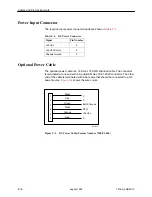
Power Input Connector
The required input power connector leads are shown in
Table C-4
.
Table C-4.
DC Power Connector
Signal
Pin Number
+24 Vdc
5
+24 Vdc Return
4
Chassis Ground
3
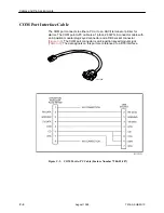
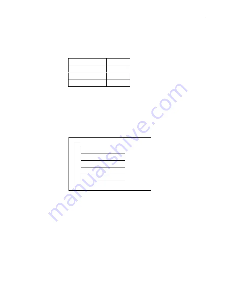
Optional Power Cable
The optional power cable is a 14.5-foot, 18 AWG stranded cable. The connector
is terminated at one end with a 6-position Molex 39-01-2060 connector. The other
end of the cable is terminated with a bare wire that should be connected to a DC
power source.
Figure C-4
shows the wire colors.
1
2
3
4
5
6
X
X
Earth Ground
RTN
+24 Vdc
X
Black
Red
Green
White
Orange
Blue
98-14158-01
Figure C-4.
DC Power Cable (Feature Number 7900-F1-506)
Содержание Hotwire 7976
Страница 42: ...Initial Startup and Configuration 3 18 7976 A2 GB20 10 August 1998 This page intentionally left blank...
Страница 56: ...Monitoring the Unit 4 14 7976 A2 GB20 10 August 1998 This page intentionally left blank...
Страница 66: ...Testing 5 10 7976 A2 GB20 10 August 1998 This page intentionally left blank...
Страница 78: ...Security 7 6 7976 A2 GB20 10 August 1998 This page intentionally left blank...
Страница 104: ...Standards Compliance for SNMP Traps B 6 7976 A2 GB20 10 August 1998...
Страница 112: ...Technical Specifications D 2 7976 A2 GB20 10 August 1998...