Managing Multiplexers
1-55
6800-A2-GB21-10
August 1994
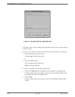
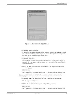
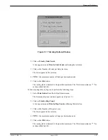
Figure 1-6. Destination Node(s) Window
2. Click on the node to be inserted.
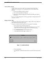
If an error window appears indicating that all nodes are present in the routing table, check
that the device and facility profiles are properly entered. These profiles must be present
before the node can be inserted in the routing table.
3. Click on the OK button.
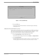
An entry for the selected destination node is inserted into the routing table in its proper
sequence. The I-bar appears in the link list area for the entry of the links associated with
this destination node.
4. TYPE: the links associated with the new destination node (separate multiple links by
commas.)
PRESS: Enter
An “*” appears in the
♦
column indicating that this destination node has been modified.
To insert a new link identifier in the link list for an existing destination node, perform the
following steps:
1. Click on the point in the link list where you want to insert the new link identifier.
The I-bar appears at that point.
2. TYPE: the new link identifier (separate multiple links by commas.)
PRESS: Enter
An “*” appears in the
♦
column indicating that this destination node has been modified.

