BA_PH_680-200_EN_11-22.docx
35
10
Mounting and Usage
10.1
Slide Table
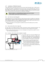
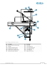
Figure 20: Slide table controls
When the sliding table saw is delivered, the slide table
is already fitted ready for operation.
•
Loosen (pull out) the remote locking device (
21
).
•
Move the slide table to the desired position.
•
Close (press in) the remote locking device (
21
).
You may have to move the slide table slightly for-
wards or backwards so that the lock engages cor-
rectly.
The safety catch (
20
) is used to move the slide table out of the saw blade area (beyond the stop) during a saw
blade change (for more information see chapter
If the machine is not used for a longer period of time, the slide table should be moved to a mid-
dle position. This prevents the rollers from being pressed in.
The slide table must not be locked during a cutting operation.
10.2
Rip Fence
The motorised rip fence is used to feed the workpiece from the rear of the machine (to the right of the saw
blade). The rip fence is already fitted when the sliding table saw is delivered. Only the aluminium profile rail
(
16
) still has to be inserted.
The operation of the rip fence is described in detail in chapter
Important:
For the operation of the rip
fence, please also observe the hazard warnings in the sections
21
20
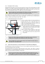
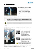
Figure 21: Fitting the rip fence
Set the aluminium profile rail for normal cuts:
•
Push the aluminium profile rail (
16
) as
far as it will go onto the two fixing
bolts (
a
) of the holding block. The
cross-section must look as shown in
the photo on the left.
•
Fix the aluminium profile rail by
means of the clamp lever (
19
). The
fence (
17
) is now ready for use.
Set aluminium profile rail for inclined saw blade:
•
Push the aluminium profile rail (
16
) onto
the holding block (
b
) rotated by 90°. The
cross-section must look as shown in the
photo on the left .
Warning! Danger of crushing between
aluminium profile rail (16) and rip fence (17).
•
Fix the aluminium profile rail by
means of the clamp lever (
17)
.
19
16
a
17
b

