background image


BA_PH_680-200_EN_11-22.docx


15


4.1.3


Residual Risks 

The machine is built according to the latest state of the art and the recognised safety rules. Nevertheless, the 
use of the machine may cause danger to life and limb of the user or third parties or damage to the machine and 
other equipment.  

Due to the construction of the machine, the following residual risks can occur even when used as intended and 
despite compliance with all relevant safety regulations: 


Reading and applying the operating manual is mandatory for the operating personnel. 


Be alert to possible crushing hazards:  
a) when transporting the machine by forklift truck 

 between forks & pallet / machine 

b) when picking up the machine 

 between machine / pallet and floor 

c) when lowering the machine 

  between machine and fixed equipment


Be alert to possible crushing hazards when lowering the machine (from the cargo pallet to the 
floor) with a forklift truck or overhead crane.


Make sure that no objects fall from the forklift truck / crane.  
Do not leave any objects / tools on the machine.


It is strictly prohibited to ride on the machine during a lifting operation (with the indoor crane or 
forklift). There is a danger of falling!


Unauthorised persons are not allowed to enter the installation area of the machine  
(responsibility of the operator).


Be aware of the danger of cutting at the saw blade. Never reach into the running saw blade! 
Always wear protective gloves when changing a saw blade.


The saw blade guard must be used resp. moved over the saw blade during every cutting oper-
ation. Cutting without using the  saw blade guard is strictly prohibited. The wearing of protec-
tive goggles is mandatory. 


Be aware of the danger from falling objects such as workpieces, tools or similar. Therefore, wear 
safety shoes, especially when transporting and setting down the machine.


Be aware of the risk of injury from flying tool parts in the event of tool breakage. 
Therefore wear protective goggles. 


Be aware of the risk of injury from flying workpiece parts and chips, splinters and dust coming out 
of the machine. Therefore wear protective goggles. 


Be aware of the increased noise emission and wear hearing protection. 


Be aware of the increased dust generation. Use the extraction device and wear a dust mask if  
necessary. 


Be aware of a possible danger of being drawn in by moving machine parts or tools. This can cause 
pieces of clothing or hair to be caught. Always wear tight-fitting clothing or avoid loose clothing 
and wear a hair net if necessary.


Danger of being drawn in and increased risk of injury when wearing watches and jewellery. 
Wearing watches and jewellery is prohibited on the tilting spindle moulder. 


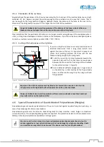
Never reach into the area between the saw blade guard and the aluminium profile rail (cross-
cut fence). There is a danger of crushing!


Electrical equipment must be maintained and cleaned regularly.


The saw blade guard for mitre cutting (inclined saw blade) is wider and can therefore be 
reached earlier by the profile rail. Therefore the danger of splintering exists earlier.


Danger from electric shock! It is strictly forbidden to bypass safety devices (e.g. safety switches).


Danger from electric shock! There are hazards when working on the electrical system.  
This work must only be carried out by qualified personnel! 


Be aware of the crushing hazard when closing the saw blade guard and the cutting hazard at the 
saw blade. 

Содержание 680|200

Страница 1: ...enbau GmbH Graf Stauffenberg Kaserne Binger Str 28 Halle 120 DE 72488 Sigmaringen Tel 49 07571 755 0 E Mail info hokubema panhans de Web https hokubema panhans de Operating Manual Sliding Table Saw PA...

Страница 2: ...4 1 5 Organisational Measures 17 4 1 6 Personnel Selection and Qualification Basic Duties 17 4 2 Safety Instructions for Specific Phases of Operation 17 4 2 1 Normal Operation 17 4 2 2 Special work wi...

Страница 3: ...up Fuses On site 32 9 Components Controls 33 10 Mounting and Usage 35 10 1 Slide Table 35 10 2 Rip Fence 35 10 3 Mounting the Cross Slide 36 10 3 1 Moving the Cross Slide 36 10 4 Use Cross Cut Fence...

Страница 4: ...ment 52 17 1 Saw Blade Height 52 17 2 Tilting the Saw Blade Angular Adjustment 53 17 2 1 Angle Compensation Tool for Mitre Cuts 53 17 3 Calibrate Saw Blade Height and Angle 54 17 3 1 Calibrate Angle 5...

Страница 5: ...Lubrication Guide 73 22 Options and Accessories 74 22 1 Sawing Units 74 22 2 Optional Fence Systems 74 22 3 Machine Operation 75 22 4 Slide Table and additional Supports 75 22 5 Support Systems 75 22...

Страница 6: ...re 38 Control elements 42 Figure 39 Start screen 44 Figure 40 Status window 44 Figure 41 Set Language 45 Figure 42 Set date and time 45 Figure 43 Rip fence positioning 46 Figure 44 Rip fence in folded...

Страница 7: ...7 Safety catch of the sawdust flap 64 Figure 88 Setting wheels for scoring saw 65 Figure 89 Calibrator Zeromaster 65 Figure 90 Laser cut position indicator 66 Figure 91 Trimming with laser beam 66 Fig...

Страница 8: ...be available at the place of use of the machine It must be read and followed by every person who is assigned to work on the machine e g during operation including set up troubleshooting in the work p...

Страница 9: ...to the obligation to wear protective goggles Non observance of these instructions may result in personal injury Reference to the obligation to wear a respiratory protection mask Non observance of the...

Страница 10: ...tenance personnel of the machine The operating personnel is to be determined by the operator and must further meet the following requirements Basic technical knowledge e g apprenticeship as carpenter...

Страница 11: ...or bypass any protective safety or monitoring equipment It is forbidden to modify or alter the machine without the written approval of the manufacturer supplier Faults or damage must be reported to th...

Страница 12: ...tactor circuit 3 7 Standard Equipment Saw motor with 5 5 kW 7 5 HP 4 speeds with saw blade 450 mm cutting height 155 mm and saw blade guard Cross cut fence on cross slide with mm scale and telescopic...

Страница 13: ...he corresponding article numbers can be found in chapter 22 3 9 Expandability The machine is prepared for the later addition of special accessories see chapter 22 from the extensive manufacturer portf...

Страница 14: ...nsultation with and approval of the manufacturer Only one piece CV or compound HM circular saw blades according to EN 847 1 with the following dimen sions are permissible as tools Saw blade min max Ma...

Страница 15: ...ictly prohibited The wearing of protec tive goggles is mandatory Be aware of the danger from falling objects such as workpieces tools or similar Therefore wear safety shoes especially when transportin...

Страница 16: ...f the machine Be aware of the risk of crushing between the sliding cross cut fence and the cross slide on both sides Do not reach into these areas Before telescoping the cross cut fence make sure that...

Страница 17: ...arly define the responsibilities of the personnel for operating setting up maintaining and repairing Ensure that only authorised personnel work on the machine If personnel to be trained or apprenticed...

Страница 18: ...dous Areas on the Sliding Table Saw Always work with all available guards and protective devices These must be accessible at the right places and in perfect working order Working position Always to th...

Страница 19: ...se a cross cut table with cross cut fence Use a deflector wedge to cut battens to length Damaged table inserts must be replaced with new ones When cutting narrow workpieces use the push stick Repairs...

Страница 20: ...Machine Another danger zone is located in front of the machine within the feed area of the saw blade Here there is a particular risk of serious injury from a material kickback During operation the op...

Страница 21: ...s into the area of the rising teeth and can be gripped Therefore generally use a fence to guide the workpiece and lower the saw blade guard to just above workpiece height 4 5 2 Never work without the...

Страница 22: ...s move the rip fence backwards towards the operator s side and fix it so that there is enough space between the fence and the front edge of the saw blade for the retraction see Figure 5 Fix an additio...

Страница 23: ...h slide table 3400 mm Main saw blade speed rpm 3000 4000 5000 6000 Cutting height at 90 max 155 mm Cutting height at 46 max 105 mm Cutting width rip fence 1250 mm Pull out cross cut fence max 3500 mm...

Страница 24: ...from 0 to 46 with mechanical length compensation all common mitre angles 15 22 5 30 45 adjustable via fixing system Electromotive rip fence with cutting width 1250 mm to the right of the saw blade pos...

Страница 25: ...y to country However this information should enable the user to make a better assessment of hazard and risk 5 3 1 Noise Emission Values The measurement values given are determined in accordance with t...

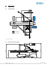
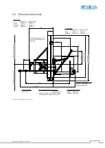
Страница 26: ...BA_PH_680 200_EN_11 22 docx 26 6 Dimensions 6 1 Working Areas Figure 7 Working areas 6 2 Dimensions Front View Figure 8 Dimensions front view Working area Removal area...

Страница 27: ...Telescopic pull out max 3500 3200 Maximum installation space Option 1440 mm Standard 1660 mm Cutting length Sliding table length Orientation dimensions A B C and D measured from the sawblade Sliding t...

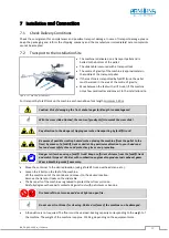
Страница 28: ...s slide Pay attention to the danger of tipping over when transporting by forklift truck Be aware of possible crushing hazards when placing the machine from the pallet to the floor by means of a forkli...

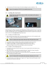
Страница 29: ...ed under the screws S Caution Crushing hazard for hands and feet when lowering setting down the machine 2 Now lower the machine completely until it is centred on the plate feet with both screws S 3 To...

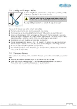
Страница 30: ...onto the loading surface that it can no longer slip The clamp ing tool should have a high STF value at the frictional connection e g long lever ratchets In addition anti slip mats should be used to pr...

Страница 31: ...an be connected to the terminals 03 and 04 of the contactor K2 Installation only by a qualified electrician The air speed must be set in such a way that with the extrac tion line connected and the too...

Страница 32: ...ocket the neutral conductor must be con nected to the terminal marked N please note N is loaded Then close the cable gland so that it is dust tight again Observe the rotational direction of the saw bl...

Страница 33: ...uction 9 Control panel 2 Swivel arm for saw blade guard 10 Swivel arm for control panel 3 Riving knife 11 Machine body 4 Sliding shoe 12 Adjustable foot 5 Sliding table 13 Cross cut fence 6 Telescopic...

Страница 34: ...ence 22 Cross slide 17 Rip fence 23 Cross slide pull out 18 Guide for motorised rip fence 24 Cross slide clamping lever 19 Clamping lever for profile rail 25 Cross slide hook in bar 20 Safety catch fo...

Страница 35: ...piece from the rear of the machine to the right of the saw blade The rip fence is already fitted when the sliding table saw is delivered Only the aluminium profile rail 16 still has to be inserted The...

Страница 36: ...concealed under the hook in bar 25 by means of the clamping lever 24 Insert the clamping rail X into the cross slide guide 26 on the slide table Fix the cross slide 22 by means of the clamping lever...

Страница 37: ...locking guide U of the cross slide 22 as shown in Figure 25 Engage the cross cut fence 13 on the cross slide 22 with the rear locking bolt K in the provided groove on the cross cut fence see Figure 27...

Страница 38: ...the cross cut fence 13 to the 15 marking on the plate 27 see Figure 29 The guide bolt B must abut against the length angle stop plate P as shown in Figure 28 and Figure 30 Now tighten the locking han...

Страница 39: ...4 Fixing wheel V for fixing the extend able fence guide I to the cross slide 5 Adjustment wheel J for the extend able fence guide I 6 Adjustment screw E for the rear flip stop Y If the fence guide is...

Страница 40: ...the exact position manually after loosen ing the fixing screws F on the bottom side Figure 35 Fixing screw Procedure Set the corresponding flip stop to any position Move a workpiece to the flip stop...

Страница 41: ...a If the mounted guard is damaged or defective b A special wider guard must be used for mitre cuts Figure 37 Fitting the saw blade guard Fitting the saw blade guard 1 Push the guard 1 to the upper mo...

Страница 42: ...o persons are in a danger zone of the machine 11 1 Control Elements The following controls are available on the control panel of the 680 200 sliding table saw Figure 38 Control elements No Description...

Страница 43: ...as the slide table is above the centre of the ma chine Furthermore the maintenance cover at the rear of the machine is equipped with a safety switch 11 4 3 Emergency Stop Switches The sliding table sa...

Страница 44: ...ne button The Setup menu is password protected and not relevant for the operator The button Training is used for the annual instruction 12 2 Status Window To open the status window press the icon on t...

Страница 45: ...ess the Service button 3 Press the button Language in the service menu 4 Select your language and confirm with Accept The new language is only adopted after the setup menu has been exited 12 3 Set Lan...

Страница 46: ...value is highlighted in red after positioning press the positioning key 2 again Warning Danger of crushing between workpiece aluminium profile rail and the slide table In the safety area the rip fenc...

Страница 47: ...Warning Danger of crushing between rip fence and table top when folding back If the rip fence is folded away no positioning is possible An error message appears in the touchscreen see section 20 2 13...

Страница 48: ...events people and objects from being crushed or jammed between the fence and the slide table Figure 47 Anti crush bar If a person or an object is between the rip fence and the slide table during posit...

Страница 49: ...the values and confirm with 7 Press the positioning button 2 8 Automatic positioning is performed 9 Press to exit the window When the scoring saw is switched off 4 it automatically moves to the waiti...

Страница 50: ...on the touchscreen refer to the following Figures 8 When the positioning button 2 flashes press it 9 The scoring saw is automatically calibrated 10 Press to exit the window Figure 50 Calibrating the s...

Страница 51: ...tion 0 Open the rear maintenance door Swivel the adjusting lever H to the right The V belt is loosened Now shift the V belt to the desired speed according to Figure 53 Rule of thumb Always change from...

Страница 52: ...17 1 Saw Blade Height Figure 55 Adjust height 1 Press symbol Height see Figure 54 2 Enter the desired target position in mm see Figure 55 3 Confirm with 4 Start the process with the positioning butto...

Страница 53: ...id a collision of the saw blade during the tilting process the rip fence must be at a position of at least 165 mm during the tilting process 17 2 1 Angle Compensation Tool for Mitre Cuts This tool aut...

Страница 54: ...with 5 Then save the value with 6 The procedure is completed Figure 58 Angular gap Figure 59 Calibrate angle Figure 60 Calibrate height 17 3 2 Calibrate Height First turn off the main switch on the co...

Страница 55: ...hazard Wear protective gloves when turning the saw blade manually 17 4 2 Calibration Procedure After the saw blade angle has been positioned at 0 0 select the Height button in the machine overview No...

Страница 56: ...l the remote locking 21 to unlock the slide table Push the slide table to the left until the stop By pressing the safety catch 20 see also section 10 1 the slide table can be moved out over the stop f...

Страница 57: ...he riving knife is missing or incorrectly adjusted there is an increased risk of injury Please also observe the hazard warnings in the section 4 5 2 Figure 68 Riving knife setting symbolic representat...

Страница 58: ...rent reference dimensions may appear in the display see example below Example Calibrating the dimensional setting Keep the buttons ENTER SET pressed at the same time The reference dimension stored in...

Страница 59: ...e enter calibration unit 4 Press ENTER The display alternates between flashing reF and the originally stored reference value here in the example o01000 0 Press SET to select the digit to be changed th...

Страница 60: ...ross cut fence Figure 79 Fix the stop plate by means of the toggle clamp lever Dismounting takes place in reverse order 19 4 Double sided Mitre Fences DSG A and DSG D With the double sided mitre fence...

Страница 61: ...h suction port for dust free working With rail for mounting height of 18 40 mm Integrated electrical magnet system to prevent tipping Tool free quick assembly disassembly on the rip fence instead of t...

Страница 62: ...idth by 0 05 mm Example The dimension 3 10 mm is to be set 1 Measure cutting width with test cut 2 Measured dimension 3 00 mm 3 Pull the knurled screw R of the mechanism forwards V turn it to the left...

Страница 63: ...urled screw forward The saw teeth must be behind each other and in the direction of rotation D The knurled screw R must be correctly engaged Place the setting mechanism onto the motor shaft screw in t...

Страница 64: ...coring saw blade Clean the flange and saw blade Insert new scoring saw blade and observe the direc tion of rotation Put on the clamping screw with flange and tighten it by hand Tighten the grub screw...

Страница 65: ...extraction Under certain conditions harmful substances can be generated in the spray mist The manufacturer s operating instructions for the spraying system must be observed Spray lubricants recommend...

Страница 66: ...position indicator 19 11 Trimming with Laser Beam To trim the workpiece as loss free as possible simply push it to the right until the edge to be trimmed is com pletely behind the laser beam Then rele...

Страница 67: ...22 Insert swivel arm support bolt B into the holding plate P of the cross slide 22 Then clamp with the clamping lever H Figure 92 Position and mount swivel arm Loosen the clamping lever 24 and pull th...

Страница 68: ...able was moved to the left over mechanical stop Move slide table to the right Power supply unit G1 defective Replace power supply unit Speed indicator shows nothing Touchscreen unit defective Contact...

Страница 69: ...le shows the possible error messages as well as their cause and remedy Figure 95 Error message 1 Message Rip fence folded down Cause Positioning of the rip fence is not possible as it is folded down T...

Страница 70: ...use Motor protection switch F1 or F2 has tripped Main motor or scoring saw motor overloaded Power supply unit G1 defective Remedy Check fuses F1 F2 and reset if necessary Check main resp scoring saw m...

Страница 71: ...axis controller Calibration procedure was not carried out properly last time New axis controller A2 installed and not yet calibrated Remedy Perform calibration procedure again Figure 108 Error message...

Страница 72: ...after you have cor rected it please call our customer service department on 0049 7571 755 0 20 3 Retightening Changing the V belt Before starting work the main switch must be switched off and secured...

Страница 73: ...ectrical equipment components weekly for externally visible damage and have them repaired by a qualified electrician if necessary Check the extraction unit for full function daily before starting work...

Страница 74: ...3 8 x 50 mm Z 12 12 set 2 pieces for the Quick Step scoring system see Art No 4550 4551 22 2 Optional Fence Systems Article Description Art No RIP FENCE WITH CAPACITY 1030 MM Automatic rip fence with...

Страница 75: ...floor rail must be available on site 4785 CUTTING LENGTH OF SLIDE TABLE 2850 MM Slide table length 2600 mm 4764 CUTTING LENGTH OF SLIDE TABLE 4050 MM Slide table length 3800 mm 4765 22 5 Support Syste...

Страница 76: ...rsonal ised RFID based keys full version for authorised and instructed per sonnel including master key for parameter settings and staff in structions and 5 user tags for machine operators 4654 PERSONA...

Страница 77: ...n laws in force at the place of use regarding the disposal of industrial solid waste toxic and hazardous waste Hoses and plastic parts as well as other components that are not made of metal must be di...

Страница 78: ...ear of manufacture in the version provided complies with the following directives Machinery Directive 2006 42 EG EMC Directive 2004 108 EG The notified body 0392 Fachausschuss HOLZ Pr f und Zertifizie...

Отзывы: