background image


BA_PH_245-10_EN_13-22.docx


16


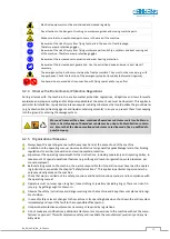
Spare parts must meet the technical requirements specified by the manufacturer. The exclusive use of 
original spare parts ensures this. Therefore, only use original spare parts from the manufacturer. 


Observe the fire alarm and firefighting possibilities. Make the location and operation of fire extinguishers 
(fire class ABC) known. Do not use water! 

4.2.6


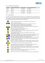
Personnel Selection and Qualification - Basic Duties 


The machine design and operation is intended for right-handers. 


Work on and with the machine may only be carried out by reliable personnel.  
Observe the legal minimum age! 


Only use trained or instructed personnel. Clearly define the responsibilities of the personnel for operating, 
setting up, maintaining and repairing! 


Ensure that only authorised personnel work on the machine! 


If personnel to be trained or apprenticed have to work on the machine, this may only be done under the 
constant supervision of an experienced resp. qualified person. 


Work on the electrical equipment of the machine may only be carried out by a qualified electrician or by 
untrained persons under the direction and supervision of a qualified electrician in accordance with the 
electrotechnical regulations. 

4.3


Safety Instructions for Specific Phases of Operation


Defects and damage to the machine are to be reported immediately after detection.


Any mode of operation that compromises safety is prohibited! 


Sufficient lighting around the machine must be ensured (at least 500 Lux)! 


4.3.1


Before Working 


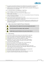
Clean the machine table from dirt and chips and provide containers for waste pieces. 


Only use tools in perfect, sharpened condition and with clean clamping surfaces. 


Always check workpieces to be machined for foreign objects, cracks and loose knots. 


Only adjust the machine ore fence when the machine is at a standstill. 


Required aids such as tool cover, power feeder, table extensions, clamping drawer,  
feed devices (e.g. push blog, push stick, bow spring, etc.) and use them as required.  


Use a power feeder whenever possible. 


Adjust the pressure devices and tool protection covers in the best possible way. 


Adjust tools only when the tool is at a standstill using a dial gauge. 


Before milling, remove any objects lying on the table (tools, spacers, etc.).  


Observe the correct direction of rotation of the tool resp. avoid dangerous climb milling. 


Use a continuous fence for safe workpiece guidance. If necessary, compensate for chip removal  
with the partial fence to ensure a continuous fence. 


Keep the floor in the area of movement around the machine free of tripping hazards. 


Ensure that the machine is connected to an extraction system. 


Wear tight-fitting clothing and safety shoes and use safety glasses and  ear protection. 


If gloves are required for workpiece handling, they must be fingerless. 


Содержание 245/10

Страница 1: ...u GmbH Graf Stauffenberg Kaserne Binger Str 28 Halle 120 DE 72488 Sigmaringen Tel 49 07571 755 0 E Mail info hokubema panhans de Web https hokubema panhans de Operating Manual Tilting Spindle Moulder...

Страница 2: ...Protection Regulations 15 4 2 5 Organisational Measures 15 4 2 6 Personnel Selection and Qualification Basic Duties 16 4 3 Safety Instructions for Specific Phases of Operation 16 4 3 1 Before Working...

Страница 3: ...1 Air Speed 28 7 6 2 Existing negative pressure at 20 m s 28 8 Electrical Connection 29 8 1 Back up Fuses on site 29 8 2 Machine Socket 29 9 Components and Control Elements 30 10 Commissioning 31 10 1...

Страница 4: ...Table Slide Plate 43 16 3 Safety Rulers for the Milling Fence 44 16 4 Swivel Away Device for the Milling Fence 44 16 5 Turntable 360 degrees for the Milling Fence 44 16 6 Extendable Frame Support 44...

Страница 5: ...ts and Control Elements 30 Figure 12 Main switch 31 Figure 13 Control panel 31 Figure 14 Unlock service door 32 Figure 15 Lock service door 32 Figure 16 Lever to release the V belt 33 Figure 17 Cuttin...

Страница 6: ...uard 1376 46 Figure 43 Angle ranges position of the screws 46 Figure 44 Adapt tenoning device drilling sketch 47 Figure 45 Kickback guard type 1648 47 Figure 46 Power feeder type PV84 48 Figure 47 Pow...

Страница 7: ...waste and maintenance during maintenance servicing inspection repair and or during transport Apart from the operating manual and the legally binding accident prevention provisions applicable in the co...

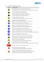
Страница 8: ...to the obligation to wear protective goggles Non observance of these instructions may result in personal injury Reference to the obligation to wear a respiratory protection mask Non observance of thes...

Страница 9: ...e or similar required The partial fence is adjusted by means of a vernier scale The optional fence type 216 has an LCD display on the handwheel to indicate the total fence position The finely planed c...

Страница 10: ...g apprenticeship as carpenter machine fitter etc and or practice in operat ing tilting spindle moulders resp woodworking machines Reading and understanding these operating and maintenance instruction...

Страница 11: ...y or bypass any protective safety or monitoring equipment It is forbidden to modify or alter the machine without the written approval of the manufacturer supplier Faults or damage must be reported to...

Страница 12: ...via RFID key system TM 100 with personalised keys Milling fence type 216 with LCD display for indicating the total fence Milling spindles 35 mm 40 mm 50 mm 1 not retrofittable Power feeder types PV84...

Страница 13: ...nger to persons and to a defect or damage to the machine Only workpieces that can be safely placed and guided may be machined Metallic materials must not be machined The machine is not suitable for op...

Страница 14: ...ger of falling Unauthorised persons are not allowed to enter the installation area of the machine responsibility of the operator Be aware of possible tripping and slipping hazards on the floor Prevent...

Страница 15: ...void leakage of hazardous substances by using suitable collection contain ers Ensure that the above mentioned substances are disposed of by a qualified dis posal company 4 2 5 Organisational Measures...

Страница 16: ...o the machine are to be reported immediately after detection Any mode of operation that compromises safety is prohibited Sufficient lighting around the machine must be ensured at least 500 Lux 4 3 1 B...

Страница 17: ...an angle of approx 5 to the feed direction and keep the opening to the fence as small as possible Manual feeding When feeding the workpiece manually place the hands flat on the workpiece with closed...

Страница 18: ...Secure the machine against unauthorised use and never leave it unattended in an unsecured condition Clean the machine with an industrial hoover avoid compressed air 4 4 Safe Working Practices Dependin...

Страница 19: ...rotation Climb milling with manual feed involves considerable dangers This operation is only permitted with ap propriate devices and suitable tools If the machine is switched to climb milling this dan...

Страница 20: ...securely fastened front cross fence as well as a kickback guard e g type 1648 see section 16 9 must also be used For very long workpieces use an auxiliary fence if necessary Quick clamps acting eithe...

Страница 21: ...ening can be adapted to the tool diameter to keep it as small as possible The service door at the front is equipped with a safety switch This prevents the milling spindle motor from being switched on...

Страница 22: ...ing workpieces workpiece parts and tool parts e g in the event of tool breakage Increased risk of in juries or even death due to entrapment of hands fingers clothing jewellery and long hair Keep hands...

Страница 23: ...Tilt Adjustment manually by handwheel Position Indicators Height Tilt analogue dial gauges in the handwheels Suction Nozzles 2 pieces 120 mm Net Weight approx 800 kg Space Requirement 1200 x 1400 mm N...

Страница 24: ...achines and other adjacent operations The permissible workstation values can also vary from country to country However this information should enable the user to make a better assessment of hazard and...

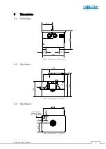
Страница 25: ...6 1 Front View Figure 3 Dimensions Front view 6 2 Top View 1 Figure 4 Dimensions Top view 1 6 3 Top View 2 Figure 5 Dimensions Top view 2 510 160 217 1000 870 1100 89 59 760 1169 1082 400 35 35 4 dril...

Страница 26: ...hazards when placing the machine from the pallet to the floor by means of a forklift truck or similar Pay particular attention to your hands and feet and wear safety shoes and protective gloves as a p...

Страница 27: ...nt Z All 4 lashing straps must be individually tensioned on the loading area The machine may only be lashed at the four lashing points Z provided Please note the following when lashing in the transpor...

Страница 28: ...traction system shown on the left apply to the standard machine Depending on the equipment or with older models these may differ The valid terminals for your ma chine can be found in the circuit diagr...

Страница 29: ...cable gland again so that it is dust tight Observe the rotational direction of the milling cutter If the cutter direction is wrong two outer conductors must be interchanged 8 1 Back up Fuses on site...

Страница 30: ...ate optionally 4 Emergency stop 14 Tilt adjustment handwheel with dial gauge 5 Milling fence type 215 15 Height adjustment handwheel with dial gauge 6 Milling splinter tab 2 x 16 Suction nozzle 120 mm...

Страница 31: ...tch 1 the speed set according to the V belt position is indicated via the re spective signal lamp D see Figure 13 The speed setting is made according to chapter 11 10 2 Rotational Direction Switch The...

Страница 32: ...hine To prevent unintentional opening of the door during operation and the associated dangers the maintenance door is equipped with a safety switch The front service door can only be opened if the saf...

Страница 33: ...E back again After the adjustment set the brake release switch back to the right hand position normal operation Please also read the chapter 18 4 Change and Tighten the Drive Belt 11 1 Cutting Speed...

Страница 34: ...quick re lease nut M with the supplied SW4 pin spanner 2 Then fully tighten the fixing screw F by hand and remove the quick release nut M by taking it out 3 Remove the spacer rings D and put on the n...

Страница 35: ...nd loop To do this move a few millimetres beyond the target position and then back to the desired position 13 2 Tilt Adjustment Open clamping star knob K1 Adjust the tilt with the handwheel 14 The ang...

Страница 36: ...ns Z is on the right side of the fence seen from the front refer to Figure 21 Figure 22 Move centrally over milling spindle Remove dirt and chips from the machine table and the underside of the fence...

Страница 37: ...always be used Remove chips and dust from the table top before adjusting the milling fence For maintenance of your fence please refer to section 18 1 14 2 1 Fence Type 215 Standard Figure 25 Operatin...

Страница 38: ...ve hood unlocking rear left 14 3 Operating the Fences The operation is identical for both fences type 215 and 216 The only difference is that with type 215 stand ard a separate measuring device e g se...

Страница 39: ...aulic swivel away device ensures comfortable safe lifting and swivelling of the milling fence The device is mounted on the table top of the machine and can be locked with the supplied key If the stand...

Страница 40: ...ained when the battery is changed IMPORTANT Observe polarity Incorrect polarity when inserting the battery leads to loss of the position value Otherwise the display unit must be recalibrated For this...

Страница 41: ...sted using the two clamping levers 9 at the rear of the fence parallel to the table top It can be mounted either above or be low the tool The height of the workpiece hold down and the contact guard 2...

Страница 42: ...gages again 15 2 TYPE 1624 CENTREX Option The protection and pressure device type 1624 CENTREX is used for the safe fixing of workpieces during manual milling operations It fits all the milling fences...

Страница 43: ...Infeed outfeed side 650 650 mm The article numbers can be found in the sec tion 20 3 Milling Fences Pos Function 1 Height adjustment 2 Fold out guide fingers 3 Move fence plates 16 2 Table Slide Plate...

Страница 44: ...machine table Figure 39 Turntable with opening for clamping At the front of the machine there is an opening 2 with a clamping screw for fixing the turntable Loosening and clamping is done with an SW6...

Страница 45: ...h the user data bank only au thorised personnel can start the machine by using a personalised RFID key Included is the TM 100 system with master key red for administrator access and four user keys blu...

Страница 46: ...lls down Wear safety shoes with steel toecaps Note for possible retrofitting If the device is retrofitted later it must be mechanically adapted to the machine table on site For this purpose the table...

Страница 47: ...s purpose two M12 threads must be fitted bore diameter 10 2 mm Fasten the tenoning device with M12 x 30 hexagon screws and washers 16 8 4 Supplementary Protective Cover 1641 Option The protective cove...

Страница 48: ...tally and vertically incl mounting cable and plug Power feeder with 4 rollers Infinitely variable feed speed from 2 18 m min as well as clockwise anti clockwise rotation Rotate to insert horizontal ve...

Страница 49: ...ace fuse wiring diagram Main switch defective Replace main switch Drive motor defective Replace motor V belt defective loose Replace or tighten belt see section 18 4 Motor protection switch has trippe...

Страница 50: ...commissioning and after signifi cant modification If the motor no longer brakes within 10 seconds when switching off it is essential to contact the customer service Do not use the machine until these...

Страница 51: ...te with a thin bodied oil if necessary X Apply a few drops of oil to the threads of the clamping adjustment levers X Clean swivel segments from resin and wood residues and lubricate with a thin bodied...

Страница 52: ...switch to the Break Release position It must now be possible to move the V belt pulley by hand By turning it you can now check whether the brake is dragging which means that it has been adjusted too...

Страница 53: ...To do this approach it step by step by first tightening the adjusting screw S only slightly in clockwise direction swinging the lever E back again and then checking the belt tension Repeat this proced...

Страница 54: ...nd secure against unintentional restarting Lock the main switch with a padlock Figure 52 Change lubricator Figure 53 Activation with activation screw Open the front service door and unscrew the used l...

Страница 55: ...rvice door monthly 2 grease shots 4 Height adjustment bearing bottom Open front service door monthly 2 grease shots 5 Chain system of the height adjustment Open front service door monthly lightly oil...

Страница 56: ...x 1375 mm extension depth approx 892 mm from the centre of the milling spindle smooth running guided in separate bearing blocks on the side of the machine table 4232 TABLE EXTENSION ON BOTH SIDES For...

Страница 57: ...ce plates ensure a guide surface without gaps for all milling operations the exact adjustment to the tool diameter and height is achieved by a stepless adjustment Usable instead of standard cast fence...

Страница 58: ...clamp and adjustable mitre fence Sliding length 710 mm height above table approx 56 mm 4547 PROTECTION COVER 1641 Protection cover for the tenoning and slotting device 1376 suitable for tool diameters...

Страница 59: ...s who are allowed to work on the machine 4655 PERSONALISED USER KEY Blue for user database TM 100 content 10 pieces 4670 MASTER KEY Red for user database TM 100 content 1 piece 4671 CENTRAL LUBRICATIO...

Страница 60: ...laws in force at the place of use regarding the disposal of industrial solid waste toxic and hazardous waste Hoses and plastic parts as well as other components that are not made of metal must be dis...

Страница 61: ...version provided complies with the following directives Machinery Directive 2006 42 EG EMC Directive 2004 108 EG Applied guidelines in particular DIN EN 848 1 The notified body 0392 Fachausschuss HOLZ...

Отзывы: