BA_PH_245-10_EN_13-22.docx
35
13
Position the Milling Spindle
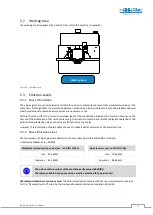
Figure 20: Handwheels for height / tilt adjustment
The positioning of the cutter height and spindle tilt is done
via the two handwheels at the front, each equipped with an
analogue dial gauge.
•
Left Handwheel
→
Tilt adjustment in degrees
Graduation: 1.0°
•
Right Handwheel
→
Height adjustment in millimetres
Graduation: 0.1 mm
13.1
Height Adjustment
•
Open clamping star knob (
K2
).
•
Adjust height with handwheel (
15
) via dial gauge (
H
).
•
After adjustment, tighten the star knob (
K2
) again.
Please note: To compensate for spindle play during height adjustment, the position should
always be approached from behind (loop). To do this, move a few millimetres beyond the
target position and then back to the desired position.
13.2
Tilt Adjustment
•
Open clamping star knob (
K1
)
•
Adjust the tilt with the handwheel (
14
). The angle is indicated on the dial gauge (
W
).
Remark:
For an angle < 0°, the zero degree lock (
17
) must be turned to the left.
•
After adjustment, tighten the star knob (
K1
) again.
The spindle for the tilt adjustment is preloaded with a gas spring. Manual spindle play
compensation (as with the height adjustment) is not necessary for adjustment.
13.3
Zero-Degree Lock
The zero-degree lock (
17
) is used to precisely return the milling spindle from the inclined position to the vertical
position (angle = 0°).
•
Turn the star knob (
17
) to the right as far as it will go and hold it in this position.
•
Turn the handwheel (
14
) clockwise (towards -5°) as far as it will go.
14
15
17
K2
K1
W
H


