©
Panduit Corp. 201
4
OPERATION MANUAL
UPS003024024015
Page: 25 of 29
4.7.1. CHARGE STATUS
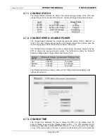
The Charge Status indicates the state of the internal energy storage of the UPS, and
closely follows the front panel CHG indicator. A table of Charge Status states is below.
4.7.2. CHARGE SPEED, CHARGE POWER
The Charge Speed indicates the current charge speed setting (“Slow”, “Medium” or
“Fast”). The “Fast” charge speed results in the fastest charge time but also uses the
most charging power which reduces the maximum load power.
The Charge Power indicates the maximum power being consumed internally by the
UPS to charge the energy storage circuitry. The table below shows the trade-off
between Charge Speed, Charge Power and Charge Time.
Charge
Speed
Maximum Charge
Power
Approximate Charging Time
Fast
53 Watts
10 minutes
Medium
37 Watts
12.5 minutes
Slow
20 Watts
20 minutes
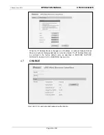
The Charge Speed can be set by clicking on the Change button immediately to the
right as shown below
4.7.3. CHARGE TIME
The Charge Time estimates the time to charge the UPS to a full charge given the
current Charge Level and the Charge Speed setting. The UPS implements cell
balancing as described in BACKGROUND
,
Section 1.1. As a result, when the voltage
on one of the twelve cells is too high, a resistor is placed across the cell to bleed the
Input
Output
Charge Status
0 VDC
0 VDC
N/A
24 VDC
24 VDC pass through
Charging
24 VDC
24 VDC pass through
Charged
0 VDC
18-22 VDC backup
Discharging
0 VDC
0 VDC
Discharged

