background image

©

 Panduit Corp. 201

4


OPERATION MANUAL 

UPS003024024015 


Page: 12 of 29 

2.2.9.  NET LED 

 Network Status Indicator 

Indicator State  

Summary 

Requirement 

Steady Off 

No Power, No IP 
address 

The device is powered off, or is powered on but with 
no IP address configured (Interface Configuration 
attribute of the TCP/IP Interface Object). 

Flashing Green 

No Connections 

An IP address is configured, but no CIP connections 
are established, and an Exclusive Owner Connection 
has not timed out.  

Steady Green 

Connected 

At least one CIP connection (any transport class) is 
established, and an Exclusive Owner Connection has 
not timed out. 

Flashing Red 

Connection 
Timeout 

An Exclusive Owner Connection for which this device 
is the target has timed out, The network status 
indicator shall return to steady green only when all 
timed out Exclusive Owner connections arc 
reestablished. 


Devices that support a single Exclusive Owner 
Connection shall transition to steady green when 
subsequent Exclusive Owner Connections are 
established 


Timeout of connections other than Exclusive Owner 
Connections shall not cause the indicator to flash red. 


The Flashing Red state applies to target connections 
only. Originators and CIP Routers shall not enter this 
state when an originated or routed CIP connection 
times out. 

Steady Red 

Duplicate IP 

For devices that support duplicate IP address 
detection, the device has detected that (at least one 
of) its IP addresses are already in use. 

Flashing Green/Red 

Self-Test 

The device is performing its power-on self-test 
(POST); During POST the network status indicator 
shall alternate flashing green and red. 

Table 2: Network Status Indicator 


2.2.10. CHG LED 

 Charge LED Status 

Green 

Charged 

Flashing Green 

Charging 

Flashing Red 

Discharging 

Red 

Discharged/Disconnected 


Содержание UPS003024024015

Страница 1: ...ons TO REDUCE THE RISK OF INJURY USER MUST READ INSTRUCTION MANUAL Email techsupport panduit com EU Website www panduit com emea EU Email emeatoolservicecenter panduit com www panduit com Technical Su...

Страница 2: ...nmental 3 Compliance 3 Installation 4 Performance 4 Indicators 5 User Interface 5 Network Interface 5 Maintenance 5 PRECAUTIONS AND GENERAL GUIDELINES 5 Safety Warnings 6 Electrical Safety Practices 6...

Страница 3: ...WORK 22 4 6 CHARGE 24 4 7 SETTINGS 26 4 8 Table of Figures Figure 1 UPS 8 Figure 2 UPS Front Panel 9 Figure 3 Reset Button Location 13 Figure 4 DIN Rail Installation 15 Figure 5 System Block Diagram 1...

Страница 4: ...ration 2G at 10 to 500 Hz Operational Shock 20G 11ms 3 bumps direction 18 bumps in total Compliance o FCC Title 47 CFR 15 Subpart B Emissions Class A o CAN ICES 3 A NMB 3 A ICES 003 Issue 5 o UL 1778...

Страница 5: ...IEC 60529 The enclosure needs to only be accessible with the use of a tool Provision shall be made to prevent the rated voltage being exceeded by transient disturbances of more than 140 at the power...

Страница 6: ...80 of original capacity 20 years at 20 C maximum UPS ambient 1 7 years at 40 C maximum UPS ambient 0 75 years at 60 C maximum UPS ambient NOTE Throughout this document the UPS003024024015 Uninterrupt...

Страница 7: ...D THE USER S AUTHORITY TO OPERATE THE PRODUCT USE RECOMMENDED ACCESSORIES CONSULT THE OWNER S MANUAL FOR RECOMMENDED ACCESSORIES THE USE OF IMPROPER ACCESSORIES MAY CAUSE RISK OF INJURY TO PERSONS Ele...

Страница 8: ...e personal protective equipment Safety glasses must be worn at all times by all persons installing the UPS Service Have your UPS serviced by a qualified repair person using only identical replacement...

Страница 9: ...EDLC cells in series and the charge voltage is applied across all cells in the series or the stack of cells Due to small differences in cell capacitance and leakage current it is possible for one cell...

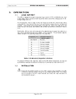
Страница 10: ...INTERFACES OVERVIEW 2 1 The physical connections to the UPS are arranged on the top edge of the front panel of the unit which includes external sense resistor connections chassis ground and the input...

Страница 11: ...upply line and the terminal marked is to be connected to the system ground The combined current draw of the UPS and the load shall not be any greater than 3 7A The operating input voltage range is 24...

Страница 12: ...teady Off No Power If no power is supplied to the device the module status indicator shall be steady off Steady Green Device Operational If the device is operating correctly the module status indicato...

Страница 13: ...only when all timed out Exclusive Owner connections arc reestablished Devices that support a single Exclusive Owner Connection shall transition to steady green when subsequent Exclusive Owner Connect...

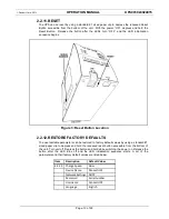
Страница 14: ...RY DEFAULTS The user settable parameters can be restored to factory default values by using a standard 1 sized paper clip to depress and hold the recessed reset button accessible from the bottom of th...

Страница 15: ...reduced as the capacitors age however the minimum run time will be supported throughout the lifetime of the capacitors The estimated capacitor lifetime is based on the operating temperature of the ca...

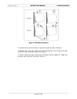
Страница 16: ...is required for proper operation of the device To install the UPS place the module with the DIN rail guide way on the top edge of the DIN rail and then snap it downwards and shown in Figure 4 To remov...

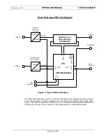
Страница 17: ...h the provided optional load sense module The AC DC converter is connected to pin 3 of the current sense resistor while pin 4 is connected to the load Figure 5 shows the pin numbering of the current s...

Страница 18: ...the load is retained The sense input and output terminals of the UPS are designed to accept UL CUL 12 to 30 AWG wire 12 gauge wires are recommended to reduce resistive losses and minimize error of the...

Страница 19: ...ay be accomplished through EthernetIP communications EtherNet IP better known as the Common Industrial Protocol CIP was designed for use in process control and industrial automation applications CIP w...

Страница 20: ...tp nnn nnn nnn nnn where nnn nnn nnn nnn is the IP address assigned to the UPS unit by the network USERNAME AND PASSWORD 4 3 When first accessing the Network Charge and Setting pages on the UPS or aft...

Страница 21: ...has not been configured the module status indicator shall be flashing green Minor Fault If the device has detected a recoverable minor fault the module status indicator shall be flashing red NOTE An...

Страница 22: ...e outside its enclosure 4 4 7 80 Capacity Years The estimated lifetime for the ELDC capacitors is 20 years for an operating temperature of 25 degrees Celsius or below The 80 Capacity parameter is init...

Страница 23: ...l as when any of the bleed resistors are turned on or off A time stamp of the Elapsed Time is recorded with each of these events The Event Log can store a maximum of 1 000 events which are stored in s...

Страница 24: ...cted that at least one of its IP addresses are already in use Self Test The device is performing its power on self test POST During POST the network status indicator shall alternate flashing green and...

Страница 25: ...IP Address an optional Network Subnet Mask and optional Gateway address can also be entered The IP Address Mode can be restored to the factory default value as described in RESTORE FACTORY DEFAULTS S...

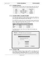
Страница 26: ...le below shows the trade off between Charge Speed Charge Power and Charge Time Charge Speed Maximum Charge Power Approximate Charging Time Fast 53 Watts 10 minutes Medium 37 Watts 12 5 minutes Slow 20...

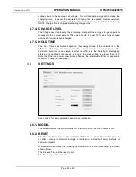
Страница 27: ...efficiency of energy conversion and the current load power consumption The estimated hold time is calculated whether the UPS is in the charging or discharging state and is updated continuously as long...

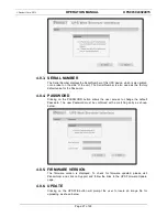
Страница 28: ...word 4 8 4 PASSWORD Clicking on the PASSWORD button allows the user access to change the default Password The new Password must be confirmed with a matching entry as shown below 4 8 5 FIRMWARE VERSION...

Страница 29: ...ter performing a firmware updated the user should immediately perform a RESET 4 8 7 MAC ID The MAC ID Ethernet adapter device identifier is displayed The MAC ID is also printed on a label affixed to t...

Страница 30: ...he WBI is displayed Clicking on the arrow displays a menu of available Languages Clicking on a different language followed by clicking on the SAVE button immediately to the right will change the Langu...

Отзывы: